G643 (E) Service Manual Chapter 3. Engine Mechanical System 68
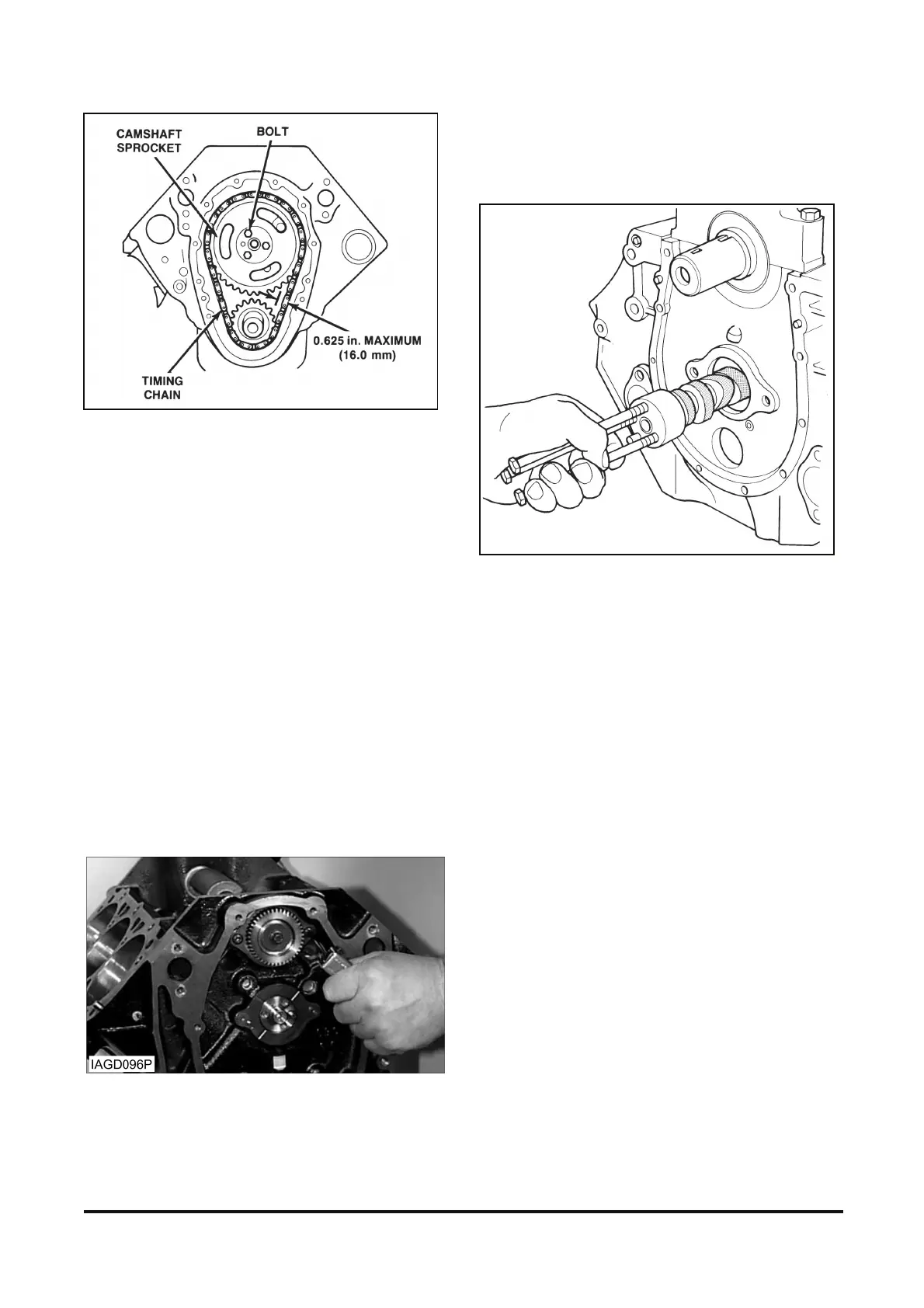
Figure 12-13 Timing Chain and Sprockets
Remove or Disconnect
1. Camshaft sprocket bolts.
2. Camshaft sprocket and camshaft timing chain
together.
IMPORTANT: The sprocket has a light inter-
ference fit on the camshaft. Tap the sprocket on
its lower edge to loosen it.
3. Balance shaft drive gear.
Camshaft Removal
Figure 12-14
Remove or Disconnect
1. Camshaft retainer bolts and camshaft retainer.
2. Camshaft.
A. Install three 5/16 - 18 bolts 100 - 125 mm (4-
5 in.) long into the camshafts threaded holes.
Use these bolts to handle the camshaft (figure
12-14).
B. Pull the camshaft out from the block being
careful to prevent damage to the camshaft
bearings.
Figure 12-14 Removing Camshaft
Balance Shaft Removal
Figures 12-15 through 12-17
Tools Required:
J 38834 Balance Shaft Bearing Service Kit
J 36996 Bearing Remover
Remove or Disconnect
1. Bolt.
2. Driven gear.
3. Retainer bolts.
4. Retainer.
5. Balance shaft using a soft faced hammer (figure
12-16).
6. Balance shaft rear bearing using J 38834 and J
36996 (figure 12-17).