G643 (E) Service Manual Chapter 3. Engine Mechanical System 104
Cylinder Head Installation
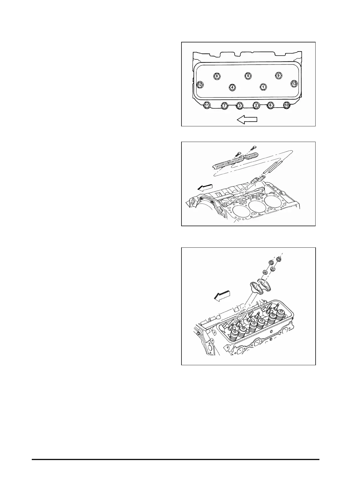
Figure 12-86
Tool Reqired:
J 36660 Torque Angle Meter
Clean
• Gasket surfaces on the block and cylinder head
Install or Connect
1. Head Gasket
IMPORTANT: Do not use sealer on head gaskets.
Place the gasket over the block dowel pins with
the head up.
2. Cylinder head. Carefully guide the cylinder head
into place over the dowel pins and gasket.
Notice: Refer to “Notice” on page 1.
3. Cylinder head bolts. Coat threads of the cylinder
head bolts with sealing compound (GM P/N
12346004) or equivalent and install fingertight.
Tighten
A. Bolts to 30 N·m (22 lb.ft.).
B. Bolts in sequence using J 36660 to:
- Short length bolt (11, 7, 3, 2, 6, 10) 55
- Medium length bolt (12, 13) 65
- Long length bolt (1, 4, 8, 5, 9) 75
4. Spark plugs.
Tighten
• Spark plug - new cylinder head to 30 N·m
(22 lb· ft.).
• All other subsequent installations to 20 N·m
(15 lb· ft.).
Valve Train Component Installation
Figure 12-87 and 12-88
IMPORTANT: Replace all valve roller lifters,
change the engine oil and filter, and add GM
Engine Oil Supplement GM P/N 1052367 (or
equivalent) to the engine oil whenever a new
camshaft is installed. Lubricate the valve lifters
bodies and roller with GM Engine Oil
Supplement GM P/N 1052367 (or equivalent)
Figure 12-86 Cylinder Head Bolt Tightening Sequence
Figure 12-87 Valve Train Components
Figure 12-88 Valve Rocker Arms and Components