G643 (E) Service Manual Chapter 3. Engine Mechanical System 86
Valve Lifters
This engine uses hydraulic valve lifters. Valve lifters
are serviced only as an assembly. No internal parts
are available. Service is limited to disassembly and
cleaning. Discard valve lifters that are excessively
worn or damaged.
IMPORTANT: Whenever the camshaft needs to
be replaced, a new set of hydraulic lifters must
also be installed.
Cylinder Head
Disassembly
Figures 12-48 and 12-49
Tool Required:
J 8062 Valve Spring Compressor
Remove or Disconnect
1. Compress the springs with J 8062
(figure 12-48).
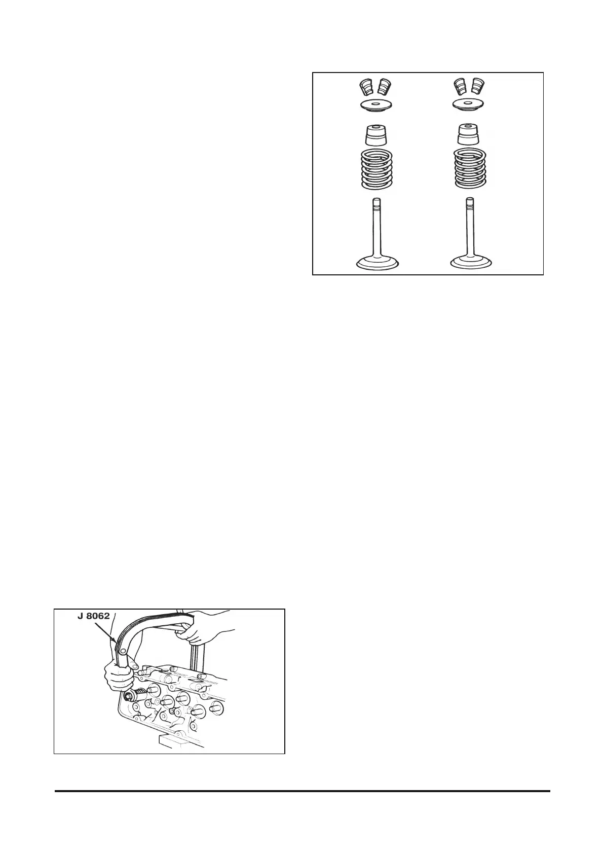
2. Keys.
3. Valve spring cap.
4. Spring.
5. Seal.
6. Valves.
IMPORTANT: Place the valves in an organizer
rack so they can be replaced in their original
position at reassembly.
Figure 12-48 Compressing Valve Springs
Figure 12-49 Valves and Components
Cleaning, Inspection, and Measurement
Figures 12-50 through 12-54
Tool Required:
J 8089 Wire brush
Clean
• Carbon from the combustion chambers using J
8089.
• Valve stems and heads on a wire wheel.
• Carbon and old gasket from the cylinder head
gasket surface.
• Valve guides using a valve guide cleaner.
Inspect
• Cylinder head for cracks in the exhaust ports,
combustion chambers, or external cracks to the
coolant chamber. Gasket surfaces should be free
of damage.
• Valves for burning, pitting, or warpage. Refer to
“Valve Grinding” in this Section. Check the valve
stems for scoring or excessive wear. Stems must
not be bent.
• Valve rocker arm studs for wear, damage, or
improper fit.
• Valve seats for pitting or other damage. Grind or
reface as needed.
• Rotators (if used). The rotators should move
smoothly without binding.
• Cylinder head for surface flatness (figure 12-51).