G643 (E) Service Manual Chapter 3. Engine Mechanical System 87
Figure 12-50 Cleaning the Combustion Chambers
Figure 12-51 Measuring Cylinder Head Surface
Measure
Tools Required:
J 8001 Dial Indicator (or equivalent)
J 8056 Valve Spring Tester
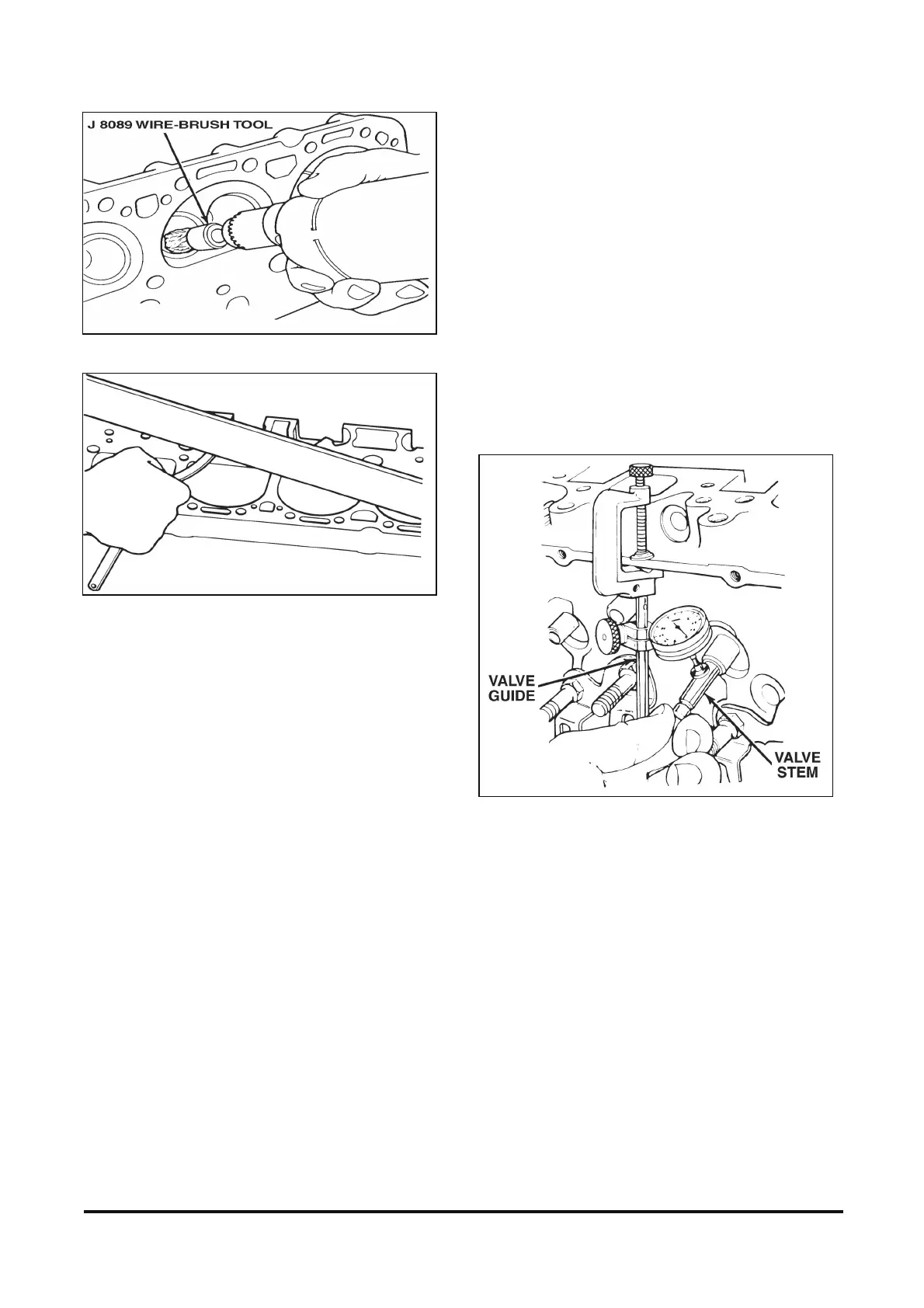
1. Valve stem to guide bore clearance.
NOTICE: Excessive valve stem to guide bore
clearance will cause excessive oil consumption and
may cause valve breakage. Insufficient clearance
will result in noisy and sticky functioning of the valve
and disturb the engine's smoothness.
A. Clamp a dial indicator (J 8001 or equivalent)
on one side of the cylinder head rocker arm
cover gasket rail.
B. Observe dial indicator movement while
moving valve from side to side (crosswise to
the head). The dial indicator measurement
must be taken just above the valve guide bore.
C. Drop the valve head about 1.6 mm (0.063 in.)
off the valve seat.
D. Move the stem of the valve from side to side
using light pressure to obtain a clearance
reading. If clearance exceeds specifications,
ream the valve guide bores for oversize valves
as outlined later.
2. Valve spring tension. Use J 8056 or equivalent.
• Compress the springs, with dampers removed,
to the specified height and check against the
specifications chart.
• Springs should be replaced if not within 44 N
(10 lb.) of the specified load.
3. Valve spring length. Replace the spring if the
length is not as specified.
Figure 12-52 Measuring Stem-to-Bore Clearance (Typical)