G643 (E) Service Manual Chapter 3. Engine Mechanical System 99
Tighten
• Balance shaft driven gear bolt to 20 Nm
(15 lb. ft.) plus an additional turn of 35° using
J 36660.
IMPORTANT: Rotate balance shaft by hand to
make sure there is clearance between the
balance shaft and retainer. If balance shaft does
not rotate freely, check to be sure retaining ring
on front bearing is seated on case. Turn the
camshaft so, with the balance shaft drive gear
temporarily installed, the timing mark on the
drive gear is straight up. With the balance shaft
drive gear removed, turn the balance shaft so
the timing mark on the driven gear points
straight down.
5. Balance shaft drive gear onto camshaft.
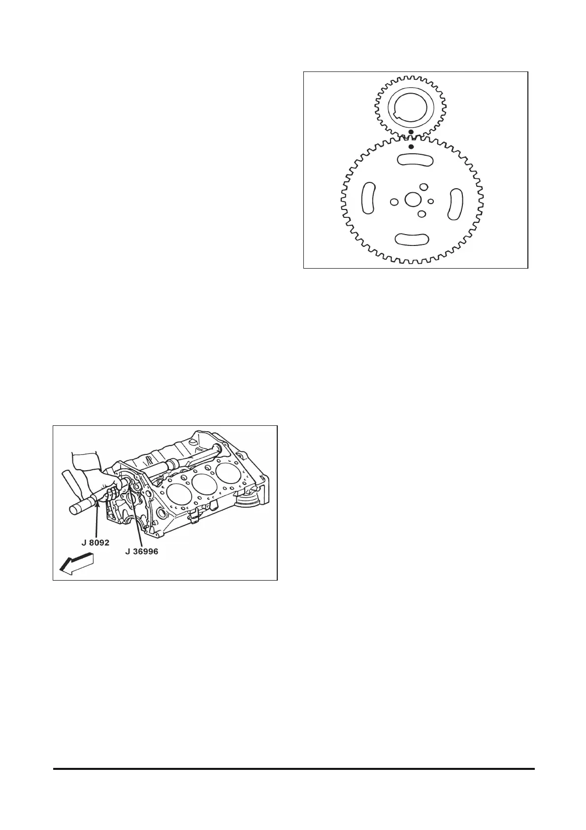
IMPORTANT: Make sure the timing marks on the
balance shaft drive gear and driven gear line up
(figure 12-76).
6. Balance shaft drive gear bolt.
Tighten
• Bolt to 16 Nm (12 lb. ft.).
Figure 12-75 Installing Balance Shaft
Figure 12-76 Balance Shaft Drive Gear-to- Driven Gear Timing
Marks
Camshaft Installation
Figure 12-77
Install or Connect
IMPORTANT: Coat camshaft lobes and journals
with Engine Oil Supplement (GM P/N 1052367) or
equivalent. Apply Engine Oil Supplement (GM
P/N 1052367) or equivalent, to all the teeth on the
distributor drive gear.
1. Install three 5/16 x 18 bolts 100 - 125 mm (4 - 5
in.) long into the camshaft threaded holes. Use
these bolts to handle the camshaft.
2. Camshaft to the engine (figure 12-77). Handle
the camshaft carefully to prevent damage to the
camshaft bearings.
NOTICE: Refer to “Notice” on page 1.
3. Camshaft retainer and retainer bolts. Coat
camshaft retainer plate with Engine Oil
Supplement (GM P/N 1052367) or equivalent.
Tighten
• Bolts to 14 Nm (124 lb. in.).