G643(E) Service Manual Chapter 5. Engine Management System (EMS) 184
Circuit Diagram (G643)
Sensor Inspection
1. Measure the voltage between terminals 1 and 4 of
the MAP sensor connectors.
Terminal 4 : MAP sensor ground
Terminal 1 : MAP sensor output
Engine state Test specification
Ignition SW. ON 4~5V
At idle 0.5~2.0V
2. If the voltage deviates from the standard value,
replace the MAP sensor assembly.
Removal
1. Disconnect the negative battery cable.
2. Disconnect the electrical connector from the
MAP/MAT sensor.
3. Remove the two screws retaining the MAP/MAT
sensor to the intake manifold.
4. Remove MAP/MAT sensor.
Installation
1. Place the MAP/MAT Sensor in position on the
intake manifold and install the two retaining
screws. Tighten retaining screws to 6 N•m (53 lbf•
ft)
2. Connect the electrical connector to the MAP/MAT
sensor. Verify that the connector clicks/locks into
place.
3. Connect the negative battery cable.
IAT (Intake Air Temperature) Sensor
[G643E and G643]
MAP sensor
The intake air temperature sensor (IAT Sensor),
built in to the MAT sensor, is a resistor-based
sensor detect the intake air temperature. According
to the intake air temperature information frim the
sensor, the ECM will control the necessary amount
of fuel injection.
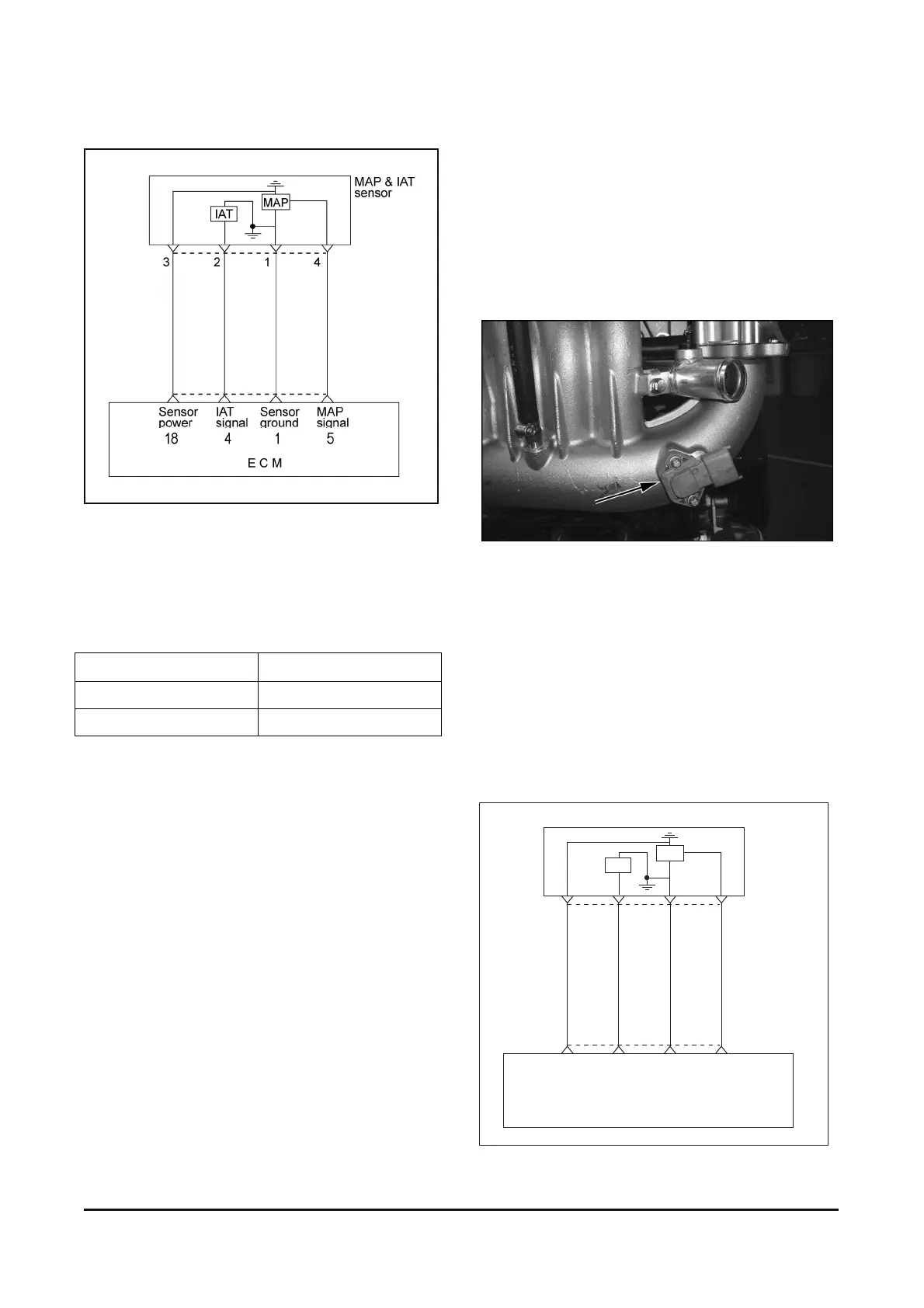
Circuit Diagram (G643E)
MAP & IAT
sensor
3214
Sensor
power
B24
IAT
signal
B12
Sensor
ground
B1
MAP
signal
B18
E C M
IAT
MAP