G643(E) Service Manual Chapter 5. Engine Management System (EMS) 183
Schematic Diagram for G643E
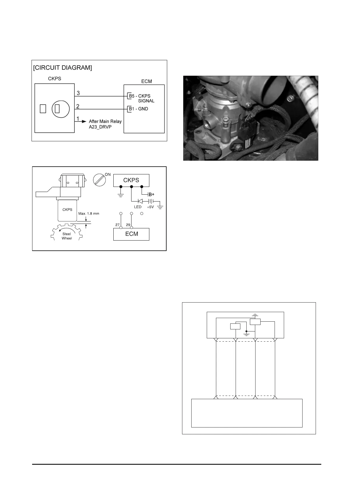
Sensor Inspection
1. Turn ignition switch to OFF position and then
disconnect CKPS connector.
2. Remove the CKPS from the engine.
3. Turn ignition switch to ON position.
4. Apply battery voltage to the terminal 1 and ground
terminal 1 and ground terminal 3 of CKPS as
shown in the figure.
5. Install a LED between +5V power and CKPS
terminal 2, and then set a steel wheel (or anything
made of steel ; hammer, wrench, bolt and nut etc.)
at the CKPS's tip.
6. Rotate the steel wheel slowly and check if the
LED flashes light.
• If the LED blinks, the CKPS works normally
MAP (Manifold Absolute Pressure)
Sensor [G643E and G643]
MAP sensor
The manifold absolute pressure (MAP) sensor is a
pressure sensitive variable resistor. It measures
changes in the intake manifold pressure which result
from engine load and speed changes, and converts
this to a voltage output. The MAP sensor is also
used to measure barometric pressure at start up,
and under certain conditions, allows the ECM to
automatically adjust for different altitudes. The ECM
supplies 5 volts to the MAP sensor and monitors the
ECM supplies 5 volts to the MAP sensor and
monitors the voltage on a signal line. The sensor
provides a path to voltage on a signal line. The
sensor provides a path to ground through its
variable resistor. The MAP sensor in put affects fuel
delivery and ignition timing controls in the ECM.
Circuit Diagram (G643E)
MAP & IAT
sensor
3214
Sensor
power
B24
IAT
signal
B12
Sensor
ground
B1
MAP
signal
B18
E C M
IAT
MAP
123