G643(E) Service Manual Chapter 5. Engine Management System (EMS) 182
Outputs
• Saturated injector drivers (4)
10A peak, 45 V max, 1 injector per channel
capable of continuous on-time
Driver circuit designed for minimum turn-on/turn-
off delay
Minimum pulse width resolution of 1 usec
• FTV drivers (2)
10A peak, 45V max. To drive an on/off fuel trim
valve with a minimum impedance of 5 ohms
Capable of continuous on-time
Drive circuit designed for minimum turn-on /turn-
off delay
FTVs will be pulse width modulated between 8
and 40 Hz with a minimum pulse width resolution
of 50 usec
• Fuel lock-off solenoid valve
Low side switch, 10A peak, 4A continuous 45 V
max
• Gasoline fuel pump drive
Low side switch, 10A, 4A continuous 45 V max
• Electronic Spark Timing (EST) (4)
TTL compatible outputs Software configured for
coil-on-plug ignition system
• Throttle control (1)
H-Bridge, 5A peak, 2.5A continuous at 2500 Hz
PWM includes current feedback for diagnostic
purposes.
• MIL (malfunction indicator lamp)
Low side switch, sufficient to drive a 7W incandes-
cent lamp continuously
• CANBus
CAN 2.0b serial communication for J1939 com-
munications, programming and diagnostics.
Requires proper termination resistance per CAN
2.0b.
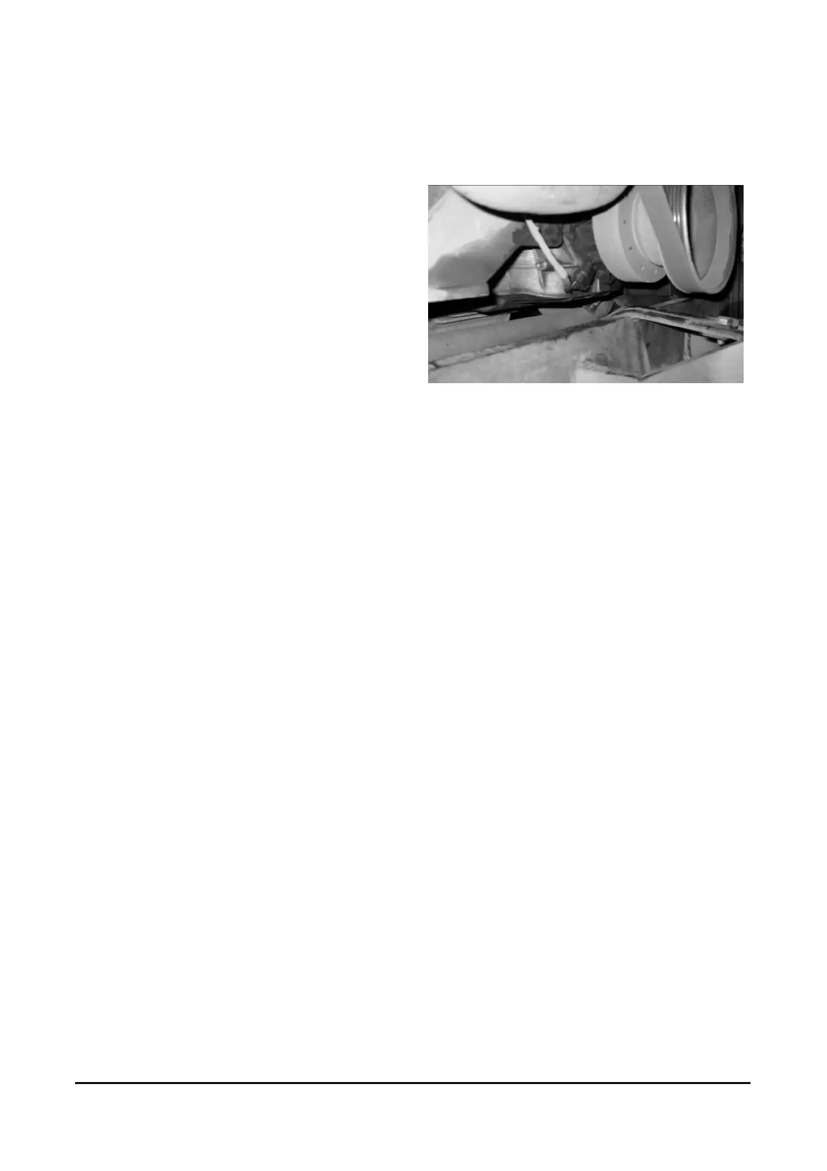
Crank Shaft Position Sensor [G643E]
Component Location
Description
The Crankshaft Position Sensor (CKPS) is a hall
effect type sensor that generates voltage using a
sensor and a target wheel mounted on the
crankshaft;
During one crankshaft rotation there are the
rectangular signals. The ECM calculates engine
RPM by using the sensor’ signal and controls the
the ignition timing.