G643 (E) Service Manual Chapter 3. Engine Mechanical System 101
Torsional Damper Installation
Figure 12-79
Tool Required:
J 39046 Torsional Damper Puller and Installer
Install or Connect
1. Apply RTV sealant GM P/N 12345739 to
crankshaft keyway (if removed).
2. Crankshaft key (if removed).
NOTICE: The inertial weight section of the torsional
damper is assembled to the hub with rubber type
material. The correct installation procedures (with
the proper tool) must be followed or movement of
the inertial weight section of the hub will destroy the
tuning of the torsional damper.
3. Stud (part of J 39046) to the crankshaft. Thread
the stud fully into the tapped hole in the
crankshaft.
4. Torsional damper over the end of the stud. Align
the keyway in the torsional damper shaft with the
crankshaft key.
5. Bearing, washer, and nut.
A. Turn the nut to pull the torsional damper into
place (figure 12-79).
B. Remove the tool.
6. Torsional damper bolt and washer.
NOTICE: Refer to “Notice” on page 1.
Tighten
• Bolt to 95 Nm (70 lb. ft.).
Figure 12-79 Installing Torsional Damper
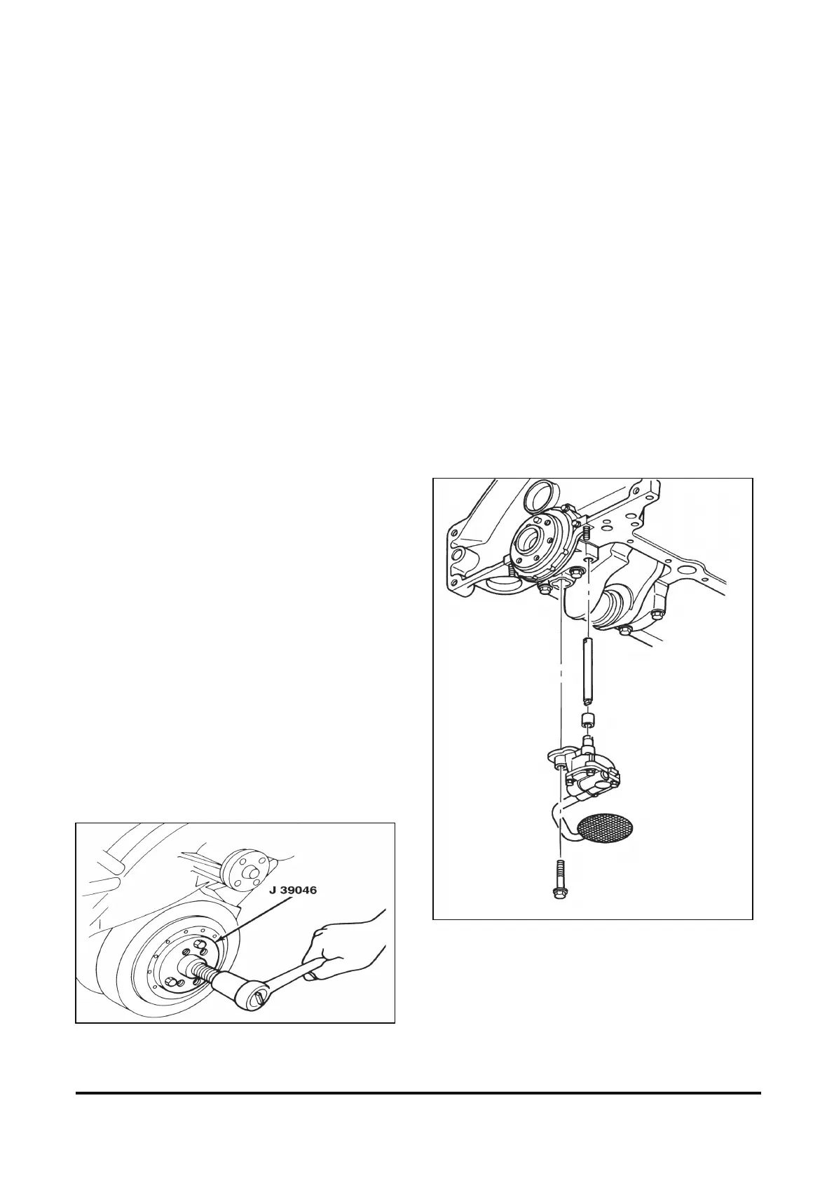
Oil Pump Installation
Figure 12-80
Install or Connect
1. Oil pump to the engine.
• Align the slot in the oil pump shaft with the tang
on the distributor shaft.
• The oil pump should slide easily into place.
• No gasket is used.
2. Oil pump to main bearing cap bolt.
NOTICE: Refer to “Notice” on page 1.
Tighten
• Oil pump to main bearing cap bolt to 90 Nm
(66 lb. ft.).
Figure 12-80 Oil Pump Installation