G643(E) Service Manual Chapter 5. Engine Management System (EMS) 185
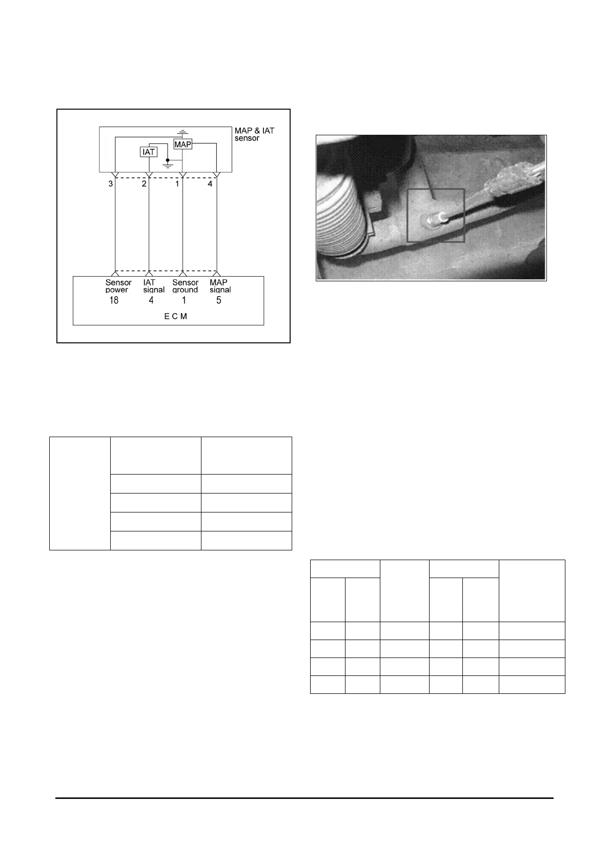
Circuit Diagram (G643)
Sensor Inspection
1. Using a multimeter, measure the IAT sensor
resistance between terminals 3 and 4.
Temperature
℃ (°F)
Resistance(kΩ)
0 (32) 4.5 ~ 7.5
20 (68) 2.0 ~ 3.0
40 (104) 0.7 ~ 1.6
IG.SW.ON
80 (176) 0.2 ~ 0.4
2. If the resistance deviates from the standard value,
replace the intake air temperature sensor
assembly.
OxygenSensor (Pre-Catalyst) [G643E]
Component Location
Pre - Catalyst Oxygen Sensor
Description
The heated oxygen sensor is mounted on the front
side of Catalytic Muffler, which detects the oxygen
concentration in the exhaust gas. The heated
oxygen sensor produces a voltage that varies
between 0V and 1V. When the air/fuel ratio is lean,
the oxygen concentration in the exhaust gas
increases and the front HO2S outputs a low voltage
(approximately0~0.1V). When the air/fuel ratio is
rich, the oxygen concentration in the exhaust gas
decreases and the front HO2S outputs a high
voltage (approximately0.8~1V). The ECM constantly
monitors the HO2S and increases or decreases the
fuel injection duration by using the HO2S signal,
which is called closed-loop fuel control operation.
Specification
Temperature Temperature
(℃)(℉)
Front
HO2S
Heater
Resis-
tance(Ω)
(℃) (℉)
Front HO2S
Heater
Resistance
(Ω)
20 68 9.2 400 752 17.7
100 212 10.7 500 932 19.2
200 392 13.1 600 1,112 20.7
300 572 14.6 700 1,292 22.5