G643(E) Service Manual Chapter 5. Engine Management System (EMS) 186
Schematic Diagram (G643E)
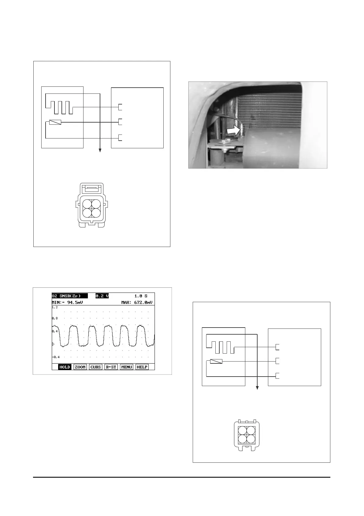
Signal Wave Form
If you release the accelerator pedal suddenly after
engine running about 2600 rpm, fuel supply will stop
for short period and the O2 sensor service data will
display values 200mV or lower. When you suddenly
press on the accelerator pedal down, the voltage will
reach 0.6 ~ 1.0 V. When you let the engine idle
again, the voltage will fluctuate between 200 mV or
lower and 0.6 ~ 1.0 V. In this case, the O2sensor
can be determined as good.
Oxygen Sensor (Post-Catalyst) [G643E]
Component Location
Description
The rear heated oxygen sensor is mounted on the
rear side of the Catalytic Muffler, which detects the
catalyst efficiency. The rear heated oxygen sensor
(HO2S) produces a voltage between 0V and 1V.
This rear heated oxygen sensor is used to estimate
the oxygen storage capability. If a catalyst has good
conversion properties, the oxygen fluctuations are
smoothed by the oxygen storage capacity of the
catalyst. If the conversion provided by the catalyst is
low due to aging, poisoning or misfiring, then the
oxygen fluctuations are similar to signals from the
front oxygen sensor.
Schematic Diagram (G643E)
[CIRCUIT DIAGRAM]
[HARNESS CONNECTORS]
C16
HO2S (
B1/S1
)
ECMHO2S (B1/S1)
After Main Relay
4
3
1
2
B13 - HO2S SIGNAL
B1 - HO2S GND
A23 - HO2S HEATER
(B1/S1)
21
43
[CIRCUIT DIAGRAM]
[HARNESS CONNECTORS]
C22
ECM
HO2S (B1/S2)
After Main Relay
3
4
2
1
B19 - HO2S SIGNAL
B1 - HO2S GND
A23 - HO2S HEATER
(B1/S2)
12
34