G643(E) Service Manual Chapter 6. LPG FUEL DELIVERY SYSTEM 198
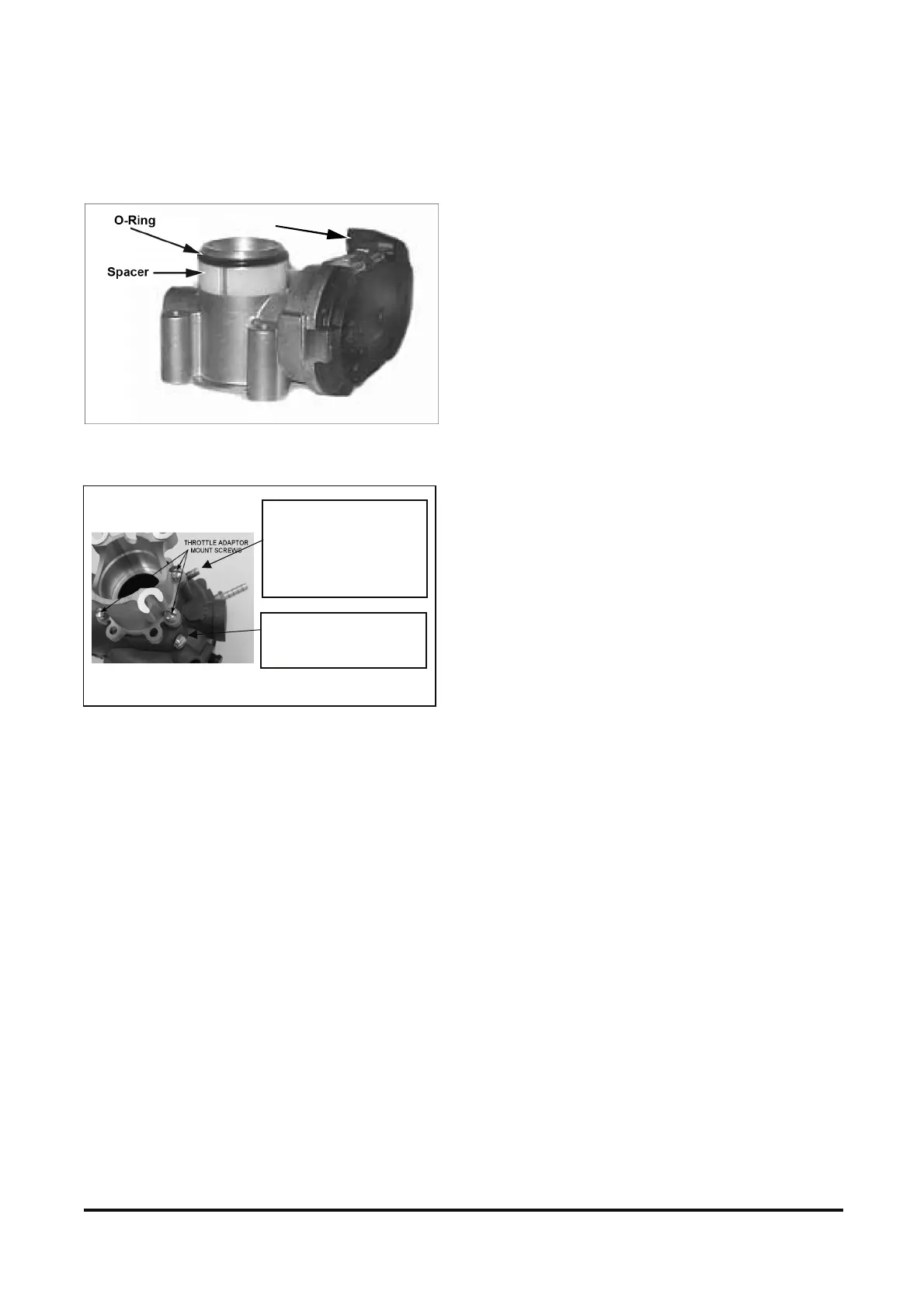
NOTE: A plastic O-ring spacer and an O-ring are
inside the mixer/adapter assembly. Be careful not to
lose these items when removing the assembly from
the throttle (Figure 31).
Figure 31. O-Ring and Spacer Within Mixer Adapter
Assembly
Figure 32. Throttle Adapter Mount Screws
CA100 Certified Mixer Installation Steps
Refer to Figure 30.
1. Install the vacuum port barb onto the mixer (9).
2. Install the fuel temperature sensor fitting (4) onto
the mixer.
3. Install the fuel temperature sensor into the fitting.
4. Ins tall the four mounting screws that attach the
throttle adapter (7) to the mixer. See Figure 32.
Torque bolts to 30-40 lbf· in (3.39-4.52 N· m).
5. Position the mixer/adapter assembly onto the
throttle body (8), then drop in the four mounting
bolts (6) and gently push down on the assembly
until it rests on the throttle body. Be careful not to
pinch the O-ring. (See Figure 31.)
6. Attach the mixer/throttle body assembly to the
intake manifold, making sure gasket is in place.
Tighten the four mounting bolts.
7. Connect the wiring harness to the throttle body.
(See Figure 31 for location of connector.) Connect
the fuel temperature sensor connector (5) to the
sensor.
8. Install the vapor fuel inlet line (3) to the fuel
temperature sensor fitting.
9. Install the two vacuum lines (2) to the mixer using
the previous marks for identification. Vacuum lines
must be installed correctly for proper operation.
10. Install the air cleaner hose (1).
VACUUM PORT BARB
Used only on certified
systems. Location may
vary depending upon
application.
ALTERNATE VACUUM
PORT BARB
Wiring harress
connection