G643(E) Service Manual Chapter 6. LPG FUEL DELIVERY SYSTEM 210
Hose Connections
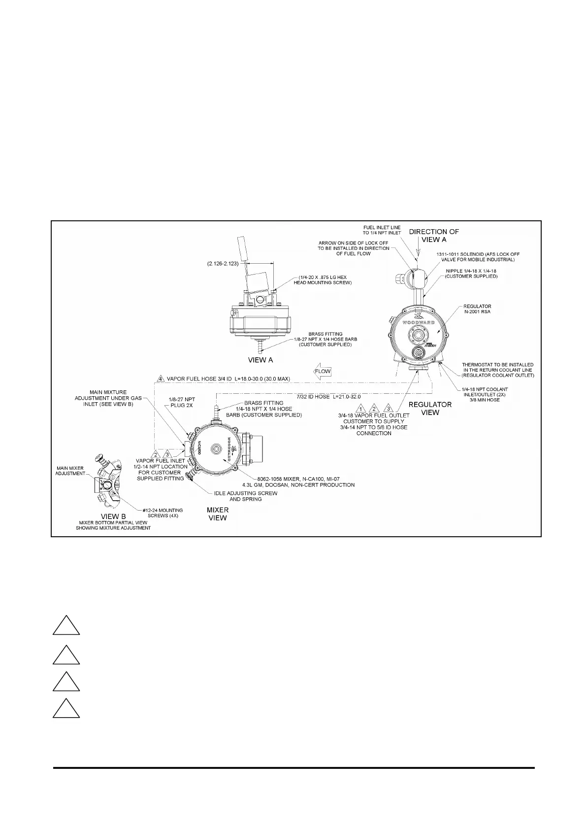
Proper operation of the closed loop control greatly depends on the correct vacuum hose routing and fuel line
lengths. Refer to the connection diagram below for proper routing and maximum hose lengths when
reinstalling system components.
NOTE: Preferred mounting of regulator is off engine.
Hose Specifications
Vacuum hose to comply to SAE 1403 Type I or SAE J30 R7 R8 / EPDM textile reinforced / -40˚ F to +257˚ F
(-40˚ C +125˚ C / Inside Diameter: 7/32” (5.56mm)
DWG NO 5555-1236
Figure 25. Hose Connections for G643 Engines
DIAGRAM NOTES
Fuel outlet must be positioned vertically in the down position
Only one 90 fitting permissible on vapor fuel line between mixer and regulator
Vapor fuel fittings (regulator and mixer) must have minimum ID of 0.59” (14.99mm)
Vapor hose length to be as short as possible and have no restrictions for best regulator performance
1
2
5