G643 (E) Service Manual Chapter 3. Engine Mechanical System 84
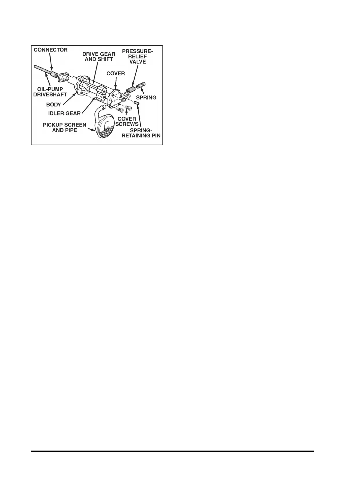
Figure 12-46 Oil Pump and Components
Clean
• All parts in clean solvent and dry them with
compressed air.
Inspect
• Pump body for cracks, wear, or other damage.
• Inside of the cover for cracks and wear that would
permit oil to leak past the ends of the gears.
• Idler and drive gears for wear.
• Drive gear and shaft for lack of fit in the pump
body.
IMPORTANT: The pump gears, cover, and body
are not serviced separately. If any of the parts
are damaged or worn, the entire oil pump
assembly must be replaced.
Inspect
• Oil pump screen damage or loose fit of the pipe.
• Pressure regulator valve for fit. The regulator
valve should slide freely in its bore without
sticking or binding.
Install or Connect
Tool Required:
J 21882 Pickup Tube and Screen Installer
1. Pressure regulator valve into the pump cover.
IMPORTANT: Replace the pressure relief valve
spring when reusing the oil pump assembly.
2. Pressure regulator spring into the pump cover.
3. Retaining pin into the pump cover.
4. Drive gear and shaft into the pump body.
5. Idler gear into the pump body.
IMPORTANT: Match together the index marks on
the two gears made during disassembly.
6. Pump cover.
NOTICE: Refer to “Notice” on page 1.
7. Bolts.
Tighten
• Bolts to 12 Nm (106 lb. in.)