G643 (E) Service Manual Chapter 3. Engine Mechanical System 89
Valve Seat Grinding
Reconditioning the valve seats is very important.
The seating of the valves must be perfect for the
engine to deliver the power and performance it was
designed to produce.
Another important factor is the cooling of the valve
head. Good contact between each valve and its seat
will ensure that heat will be carried away properly.
Several different types of equipment are available
for refacing valves. The manufacturer's instructions
for how to use the equipment should be carefully
followed to attain the proper results.
Regardless of what type of equipment is used, it is
essential that valve guide bores be free from carbon
or dirt to ensure proper centering of the pilot in the
guide. Refer to “Specifications” for valve seat angle
specifications.
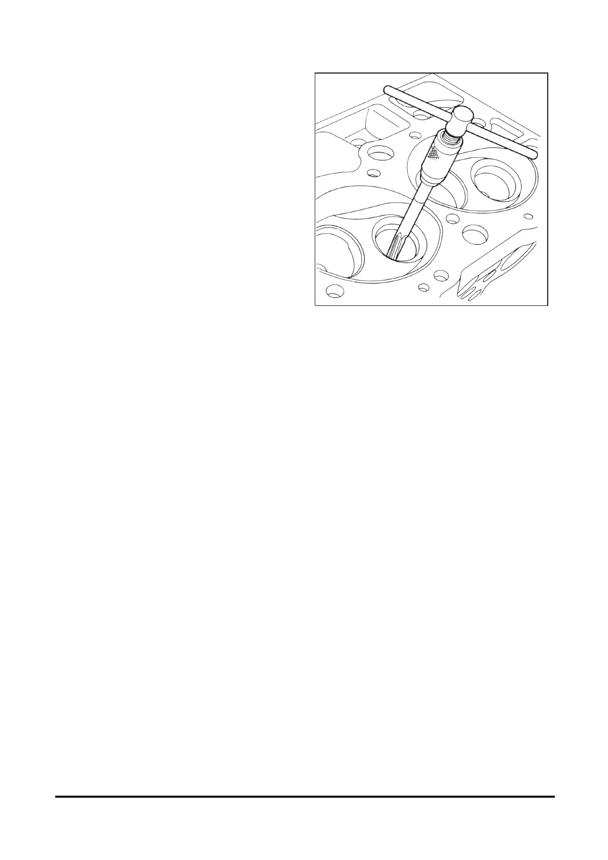
Reaming Valve Guide
The valve guides used in this engine are simply
holes bored in the cylinder head. The valve guides
are not replaceable.
If the valve stem-to-bore clearance as previously
measured is excessive, the valve guides should be
reamed and a valve with an oversize stem installed.
Oversize valves are available. Refer to “Specifica-
tions”.
Select a reamer that will provide a straight, clean
bore through the entire length of the valve guide
(figure 12-58).
Valve Rocker Arm Stud Replacement
Remove or Disconnect
1. Valve rocker arm stud by unscrewing.
Install or Connect
1. Valve rocker arm stud into cylinder head.
Tighten
• Rocker arm stud to 47 Nm (35 lb· ft.).
Figure 12-58 Reaming Valve Guides
Assembly
Figures 12-48, 12-49, 12-59 and 12-60
Install or Connect
1. Valves.
A. Lubricate the valve stems with clean engine
oil.
B. Insert the valves into the proper valve guides
until the face of the valve contacts the valve
seat.
2. Seal.
A. Install the seal over the valve stem.
B. Hold the valve against the valve seat.
C. Push the seal down the valve stem until it
bottoms out against the head.
3. Springs.
4. Valve spring cap.
A. Compress the valve spring using J 8062
(figure 12-48), enough so the lower valve stem
groove can be seen clearly.
B. Apply a small amount of grease to the area of
the upper valve stem groove.
C. Assemble the two valve keys into the upper
groove using the grease to hold them in place.
D. Release the compressor tool J 8062, making
sure the valve keepers stay in place.
E. Repeat the preceding steps on the remaining
valves.