1BHFt%3*45&&.7BQPSMPHJD*OTUBMMBUJPOBOE0QFSBUJPO.BOVBM
Float valve system
DI/RO water systems (except for steam injection) use a float valve
system to control water levels for optimum operating efficiency.
DI/RO systems are used where water/steam purity is important,
where demineralized water is needed to improve performance or
lessen maintenance requirements, or where a water source has
minimal or no conductivity, thus requiring a float rather than a
probe to sense water levels.
The float valve system consists of a fill float and a low water cutoff
float.
The fill float regulates how much water is added to the tank via a
float ball, float arm, and mechanical valve. The valve is adjusted to
fill the evaporating chamber within ¼" (6 mm) of the overflow port
allowing heated, and therefore expanded, water at startup to fill the
external P-trap.
The low water cutoff float has an electrical switch that closes when
a ready water condition is reached. This float switch provides low
water protection for the heating outputs. If the water falls below the
float, the heating outputs are disabled.
See “Chloride corrosion” Caution at left.
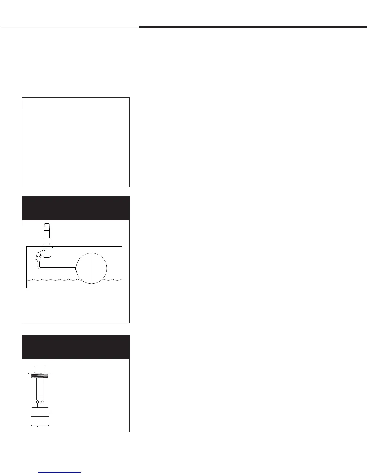
Figure 56-1:
Water level control for DI/RO
water systems
Figure 56-2:
Low water cutoff switch for DI/RO
water systems
8BUFSMFWFMDPOUSPM
Operation
Supply water connection
Float rod
Float ball
OM-7396
Humidifiers using DI/RO water control water
levels using a float valve and low-water
cutoff switch.
mc_052710_1644
A zero mark on top of the
float indicates proper float
placement on stem. Switch
is normally open when float
ball is at its lowest point on
the stem.
OM-3009
XT humidifiers do not use the float valve system
for water level control. See “Electrode steam
humidifiers” on Page 57.
CAUTION
Chloride corrosion
Damage caused by chloride corrosion is
not covered by your DRI-STEEM warranty.
Chloride corrosion can result from a
variety of causes, including, but not
limited to
t *NQSPQFSXBUFSEFJPOJ[BUJPOQSPDFTTFT
t *NQSPQFSXBUFSTPGUFOJOHQSPDFTTFT
t )VNJEJmFSTTVQQMZXBUFS
 Loading...