1BHFt%3*45&&.7BQPSMPHJD*OTUBMMBUJPOBOE0QFSBUJPO.BOVBM
4UFQo'JFMEXJSJOH
-JNJUDPOUSPMT
Airflow proving switch
Connect wiring for a duct, Space Distribution Unit (SDU) airflow
proving switch by inserting wires into the terminal block plug at
P13 (labeled AFsw and 24) per the wiring diagram on the next
page. Tighten screws; maximum torque is 3 in-lb (0.34 N-m).
(An SDU is a cabinet fan dispersion assembly.)
See also “Sensor placement” on Page 26.
Duct high limit switch or transmitter
Connect wiring for a duct high limit switch or transmitter by
inserting wires into the terminal block plug at P13 (labeled DHL
and 24) per the wiring diagram on the previous page. Tighten
screws; maximum torque is 3 in-lb (0.34 N-m).
Note: The duct high limit sensor connected at this location can
be an on-off high limit switch, or it can be a duct high limit
transmitter with an adjustable high limit set point (4-20 mA input).
See also “Sensor placement” on Page 26.
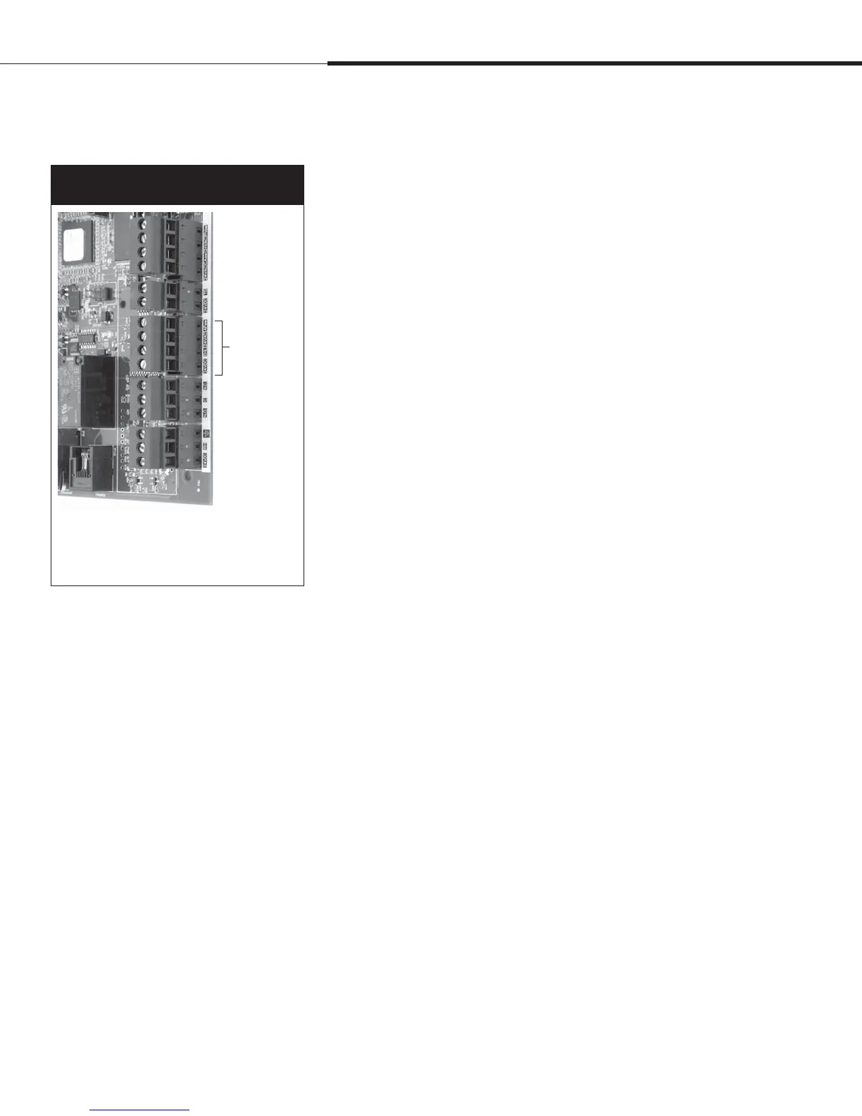
Terminal P13
Figure 16-1:
Terminal P13
Terminal P13:
24VDC = Power to duct high limit switch or transmitter
DHL = Duct high limit switch/transm. (4-20 mA input)
24
VAC = Power to airflow proving switch
AFsw = Airflow proving switch (24 VAC Input)
Installation
 Loading...