%3*45&&.7BQPSMPHJD*OTUBMMBUJPOBOE0QFSBUJPO.BOVBMt1BHF
Vapor-logic4 keypad/display
If your keypad/display is factory-mounted and connected to the
Vapor-logic4 board, proceed to installing the next device required
by your system.
If your keypad/display was shipped loose, mount the keypad/
display in a location so that the provided cable is long enough to
connect the keypad/display to the Vapor-logic4 board.
To connect a Vapor-logic4 keypad/display to the Vapor-logic4
board, insert the male end of the provided cable into the
Vapor-logic4 board at Terminal P10 (labeled Display) until you
hear a click sound (see also the wiring diagram on the next page).
Plug the other end of the cable into the keypad/display. This
connection provides DC power and communication to the keypad/
display.
See Caution at right before routing cable.
If a longer keypad/display cable is needed, order a replacement
cable from DRI-STEEM (see the replacement parts section of this
manual), or use a four-conductor straight-through cable or a six-
conductor, crossover, twisted pair cable connected to an RJ11 jack.
Note required operating conditions listed on Page 3.
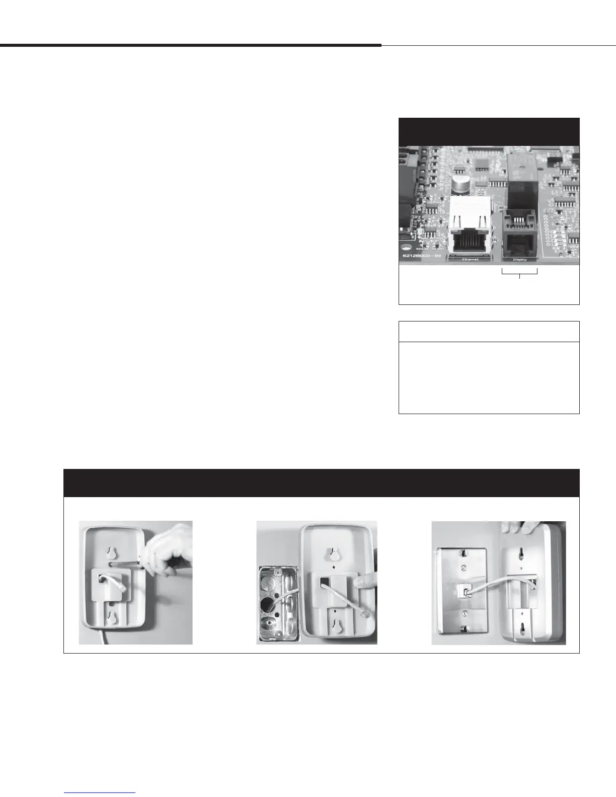
Other than factory-mounted, there are three ways to mount the
keypad/display. See Figure 19-2.
4UFQo'JFMEXJSJOH
$PNNVOJDBUJPODPOOFDUJPOT
Terminal P10:
Display
Figure 19-1:
Terminal P10
Mount keypad/display back directly to wall
Mount keypad/display back to junction box
Mount keypad/display back to phone plate
Figure 19-2:
Mounting the keypad/display
Installation
CAUTION
Keypad/display cable
Maximum cable length is 500’ (152 m).
When routing keypad/display cable, route
cable away from all power wiring.
 Loading...