1BHFt%3*45&&.7BQPSMPHJD*OTUBMMBUJPOBOE0QFSBUJPO.BOVBM
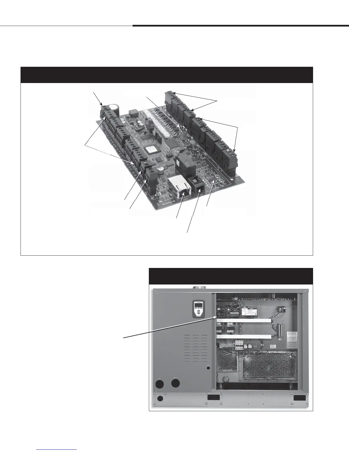
Vapor-logic4 control board
The Vapor-logic4 control board is
mounted inside the humidifier control
compartment or cabinet.
Notes:
t$POUSPMCPBSEJTTIPXOIFSFNPVOUFE
on a GTS humidifier subpanel.
Location varies with humidifier type.
t$POUSPMCPBSEGPSFMFDUSJDIVNJEJGJFST
is in the control cabinet or on the
humidifier’s subpanel.
7BQPSMPHJDCPBSE
$PNQPOFOUT
The photo above shows key components of the Vapor-logic4 control board. See the illustration on the next page for more detail.
Figure 4-1:
Vapor-logic4 control board
Power to board connection
Factory connection points
for drain, steam valve, etc.
USB connection
Field connection points for
transmitters, power vent, etc.
Field connection terminal labels
have a white border.
Optional LonTalk
module location
Ethernet connection
for computer network
and/or BACnet/IP
Keypad/display
connection
BACnet or Modbus
connection
Factory connection points
for water level control,
gas valves, etc.
DRI-STEEM RS485
connection
Figure 4-2:
Control board mounted on GTS subpanel
Overview
 Loading...