1BHFt%3*45&&.7BQPSMPHJD*OTUBMMBUJPOBOE0QFSBUJPO.BOVBM
1SFJOTUBMMBUJPO$IFDLMJTU
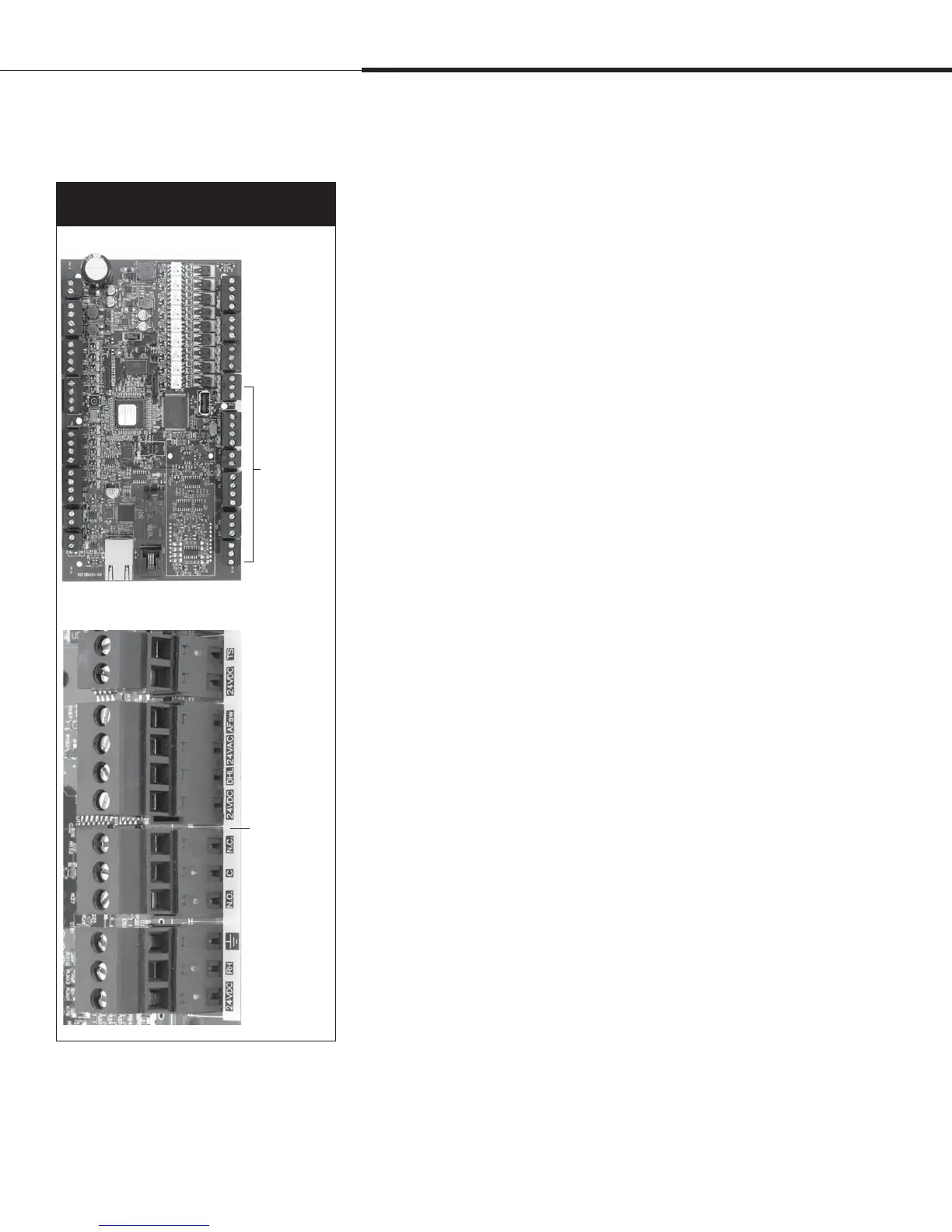
See Figure 8-1 for field terminal block locations. Note that field
wiring connection locations on the Vapor-logic4 board are
surrounded with a white border.
See the figure on the next page for instructions on how to make
wiring connections.
See the wiring drawings and manuals that shipped with your
humidifier.
When making field connections, do not route low voltage wires
near line voltage wires. Do not route low voltage wires in the
same conduit as line voltage wires.
Humidistat, room/duct transmitter, temperature sensor, and
airflow proving switch wiring must be minimum 18-gauge
(1 mm
2
) plenum rated, shielded (screened), twisted pair wire
with a bare drain wire for grounding.
Connect the shield (screen) wire [with a length less than 2"
(50 mm)] to the shield (screen) ground terminal on the electric
subpanel. Do not ground the shield (screen) wire on the
humidistat or transmitter end.
If you have a remote-mounted control cabinet, the water
level control device, thermal trip, safety interlock, fill valve,
and drain valve wiring must be minimum 18-gauge (1 mm
2
)
stranded wire run in a conduit separate from power wires.
Do not use shielded (screened) cable for water level control
devices.
When the control cabinet is mounted remotely from the
humidifier, connect a ground wire from the machine ground
lug on the humidifier to the machine ground lug in the control
cabinet. The bonding machine ground wire should be the same
AWG (mm
2
) as the largest heater wire (electric humidifiers)
or sized per local code, National Electrical Code (NEC), or in
Europe, IEC 60364 requirements.
Figure 8-1:
Vapor-logic4 control board detail
Board detail showing white border
Terminals P-11
through P-16
have a white
border on the
Vapor-logic4
board. This
is where you
will make
most of your
field wiring
connections.
Full board
Field
connection
terminals have
labels printed
on a white
border.
Installation
 Loading...