DSE Model 4110 AutoStart Operators Manual
057-022 4110 OPERATING MANUAL ISSUE 5.1 18/06/2007 JR 19
9 ELECTRICAL CONNECTIONS
Connections to the Module are via plug and sockets.
9.1 CONNECTION DETAILS
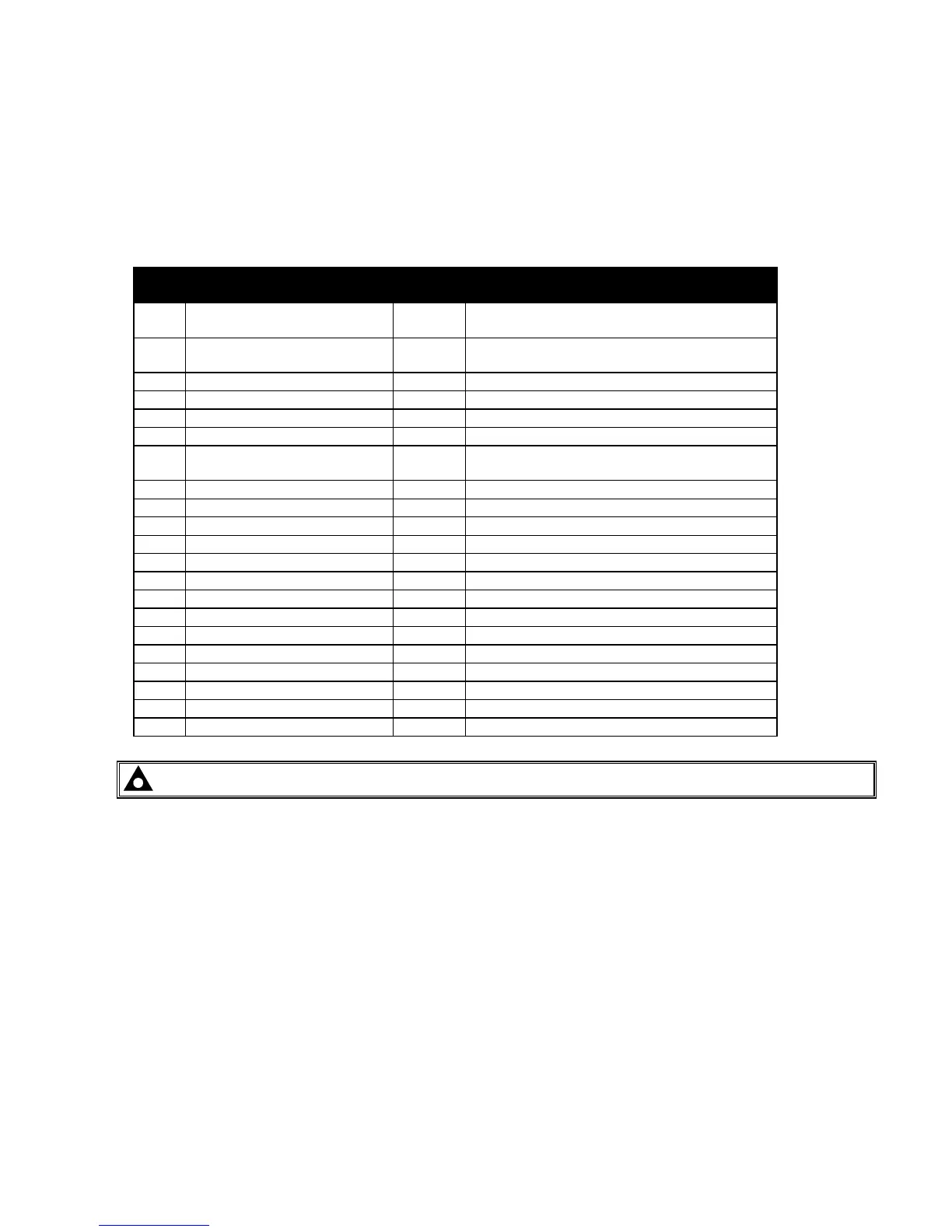
The following describes the connections and recommended cable sizes to the 2 plugs and sockets on the rear of
the Module. See rear panel layout FIG 6.
PIN
No
DESCRIPTION CABLE
SIZE
NOTES
1
DC Plant Supply Input
(-ve)
1.0mm
Connected to plant battery negative
2
DC Plant Supply Input
(+ve)
1.0mm
Connected to plant battery positive
(Recommended Fuse 2A)
3
Fuel Solid State Output
1.0mm
Used to operate the fuel relay.
4
Start Solid State Output
1.0mm
Used to operate the cranking relay.
5
Auxiliary Solid State Output 1
1.0mm
Configurable output.
6
Auxiliary Solid State Output 2
1.0mm
Configurable output.
7
Charge Fail Input/ Excitation
Output
1.0mm
Must NOT be connected to plant supply
negative if not used.
8
Low Oil Pressure Input
0.5mm
Switch to negative.
9
High Engine Temp Input
0.5mm
Switch to negative.
10
Auxiliary Input 1
0.5mm
Switch to negative.
11
Auxiliary Input 2
0.5mm
Switch to negative.
12
Automatic start Input
0.5mm
Switch to negative.
13
Not used
14
Not used
15
Functional Earth
1.0mm
Connect to a good clean earth point
16
Not used
17
Not used
18
Not used
19
Not used
20
Alternator Input L1
1.0mm
Do not connect if not used. (2A Fuse)
21
Alternator Input N
1.0mm
Do not connect if not used.
NOTE:- All the outputs are solid state, rated at 1.2 Amps and switch to battery negative when active.