DSE Model 4110 AutoStart Operators Manual
057-022 4110 OPERATING MANUAL ISSUE 5.1 18/06/2007 JR 25
14 APPENDIX
14.1 SOLID STATE OUTPUTS
DSE’s utilisation of Solid State Outputs gives many advantages, the main points being:
♦ No Moving Parts
♦ Fully Overload / Short Circuit Protected.
♦ Smaller dimensions hence lighter, thinner and more cost effective than conventional relays.
♦ Lower power consumption hence increased reliability.
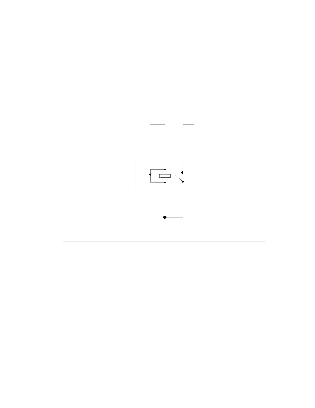
The main difference from conventional outputs is that solid state outputs switch to negative (–ve) when active. This
type of output is normally used with an automotive or plug in relay.
Battery positive (+)
Solid state output from DSE module
eg. Terminal 3 of 4110 - FUEL
Fuel Solenoid
(+ terminal)
* Observe polarity when using
relays fitted with integral diodes!
*
A
D
B
C
A
B
C
D
Solid State Output
from DSE Module Pin
Automotive
relay Pin
8 Pin Plugin relay Function
3 86 7 Fuel Output
85 2 To Positive supply via fuse
30 1 To Positive supply via fuse
87 3 To Fuel Solenoid
Example of relay pins connected to DSE solid state output to drive a fuel solenoid.
See section on Typical Connections else where in this manual for overall typical wiring diagram