DSE Model 4110 AutoStart Operators Manual
057-022 4110 OPERATING MANUAL ISSUE 5.1 18/06/2007 JR 21
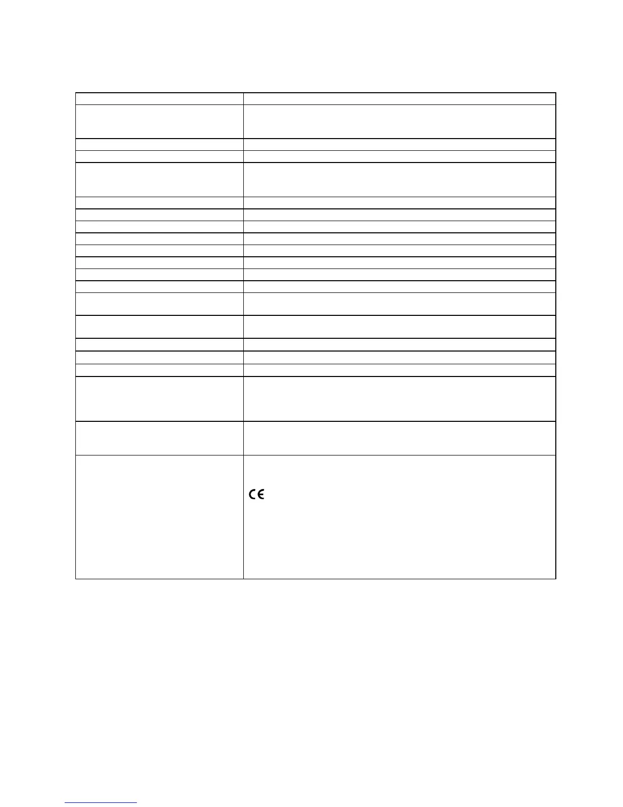
10 SPECIFICATION
DC Supply
8.0 to 35 V Continuous.
Cranking Dropouts
Able to survive 0 V for 50mS, providing supply was at least 10 V before
dropout and supply recovers to 5V. This is achieved without the need
for internal batteries.
Typical Standby Current
20A at 12 V. 20A at 24 V.
Max. Operating Current
150A at 12 V. 250A at 24V
Alternator Input Range
Single phase 2 wire system
15V AC - 277 V AC (ph-N) (+20%)
3Phase 4Wire System
15V AC - 277 V AC (ph-N) 3 Phase 4wire (+20%)
Alternator Input Frequency
50Hz - 60 Hz at rated engine speed
Start solid state Output
1.2 Amp DC at supply voltage. Switched to negative
Fuel solid state Output
1.2 Amp DC at supply voltage. Switched to negative
Auxiliary solid state Outputs
1.2 Amp DC at supply voltage. Switched to negative
Dimensions
Panel cutout
154mm x 98mm ( 6.1” x 3.9”) Maximum panel thickness 8mm (0.3”)
Charge Fail / Excitation Range
12 Volts = 8 Volts CF 24 Volts = 16 Volts CF
Operating Temperature Range
-30 to +70°C
Electromagnetic Compatibility
BS EN 50081-2 EMC Generic Emission Standard (Industrial)
BS EN 50082-2 EMC Generic Immunity Standard (Industrial)
Electrical Safety
BS EN 60950 Safety of I.T. equipment, including electrical business
equipment.
Cold Temperature
BS EN 60068-2-1 to -30
o
C
Hot Temperature
BS EN 60068-2-2 to +70
o
C
Humidity
BS2011-2-1 to 93% RH @ 40°C for 48 Hours
Vibration
BS EN60068-2-6
10 sweeps at 1 octave/minute in each of 3 major axes.
5Hz to 8Hz @ +/-7.5mm constant displacement
8Hz to 500Hz @ 2gn constant acceleration
Shock
BS EN 60068-2-27
3 Half sine shocks in each of 3 major axes
15gn amplitude, 11mS duration
Applicable Standards
Compliant with BS EN 60950 Low Voltage Directive
Compliant with BS EN 50081-2: 1992 EMC Directive
Compliant with BS EN 61000-6-4: 2000 EMC Directive
Compliance to European Legislation