DSE Model 5210 Automatic Start Engine Management and Instrumentation System Operators Manual
28 057-011 5210 OPERATING MANUAL ISSUE 5.1 18/06/2007 AM
9 ELECTRICAL CONNECTIONS
Connections to the Module are via plug and sockets.
9.1 CONNECTION DETAILS
The following describes the connections and recommended cable sizes to the 7 plugs and sockets on the rear of
the Module. See rear panel layout FIG 6.
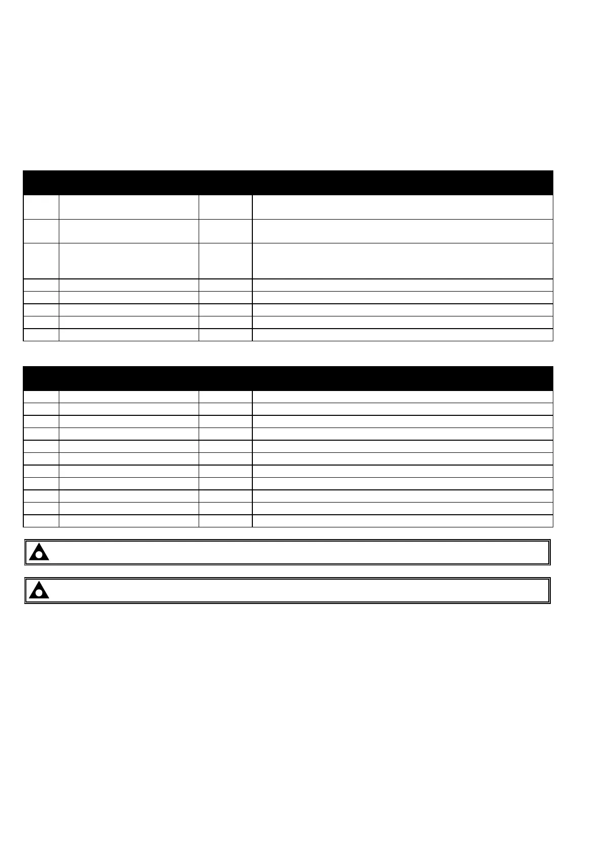
9.1.1 PLUG “A” 8 WAY
PIN
No
DESCRIPTION CABLE
SIZE
NOTES
1 DC Plant Supply Input
(negative)
2.5mm
2 DC Plant Supply Input
(positive)
2.5mm (Recommended Maximum Fuse 21A)
3 Emergency Stop Input 2.5mm Plant Supply positive. In addition, supplies fuel & start
outputs.
(Recommended Maximum Fuse 32A)
4 Fuel relay Output 2.5mm Plant Supply positive from pin 3. 16 Amp rated.
5 Start relay Output 2.5mm Plant Supply positive from pin 3. 16 Amp rated.
6 Auxiliary Output relay 1 1.0mm Plant Supply positive. 5 Amp rated.
7 Auxiliary Output relay 2 1.0mm Plant Supply positive. 5 Amp rated.
8 Auxiliary Output relay 3 1.0mm Plant Supply positive. 5 Amp rated.
9.1.2 PLUG “B” 11 WAY
PIN
No
DESCRIPTION CABLE
SIZE
NOTES
9 Charge fail / excite 2.5mm Do not connect to ground (battery –ve)
10 Auxiliary input 1 0.5mm Switch to negative
11 Auxiliary input 2 0.5mm Switch to negative
12 Auxiliary input 3 0.5mm Switch to negative
13 Auxiliary input 4 0.5mm Switch to negative
14 Auxiliary input 5 0.5mm Switch to negative
15 Auxiliary input 6 0.5mm Switch to negative
16 Functional Earth 2.5mm Connect to a good clean earth point
17 Magnetic pickup positive 0.5mm Connect to Magnetic Pickup device
18 Magnetic pickup negative 0.5mm Connect to Magnetic Pickup device
19 Not connected -
NOTE:- Ensure magnetic pickup screen is connected to ground at one end only.
NOTE:- Connector C is not fitted to the 5210 remote start module.
CALL US TODAY
1-888-POWER-58
REQUEST A QUOTE
parts@genpowerusa.com
SHOP ONLINE
www.genpowerusa.com