DSE Model 5210 Automatic Start Engine Management and Instrumentation System Operators Manual
057-011 5210 OPERATING MANUAL ISSUE 5.1 18/06/2007 AM 41
16 APPENDIX
16.1 ALTERNATIVE WIRING TOPOLOGIES
The 5200 series controllers can support many different wiring topologies (AC systems) to suit the many systems in
use world-wide. The ‘Typical connection diagram’ details how to connect the module when used in a 3 phase, 4
wire system (3 phase star connected alternators). Changes to this typical wiring diagram for other AC systems are
detailed below.
NOTE:- The factory default configuration for the 5210 module is for use with the 3 phase, 4 wire AC
system. If another system is to be used, the controller must be reconfigured using the 5200 series
configuration software.
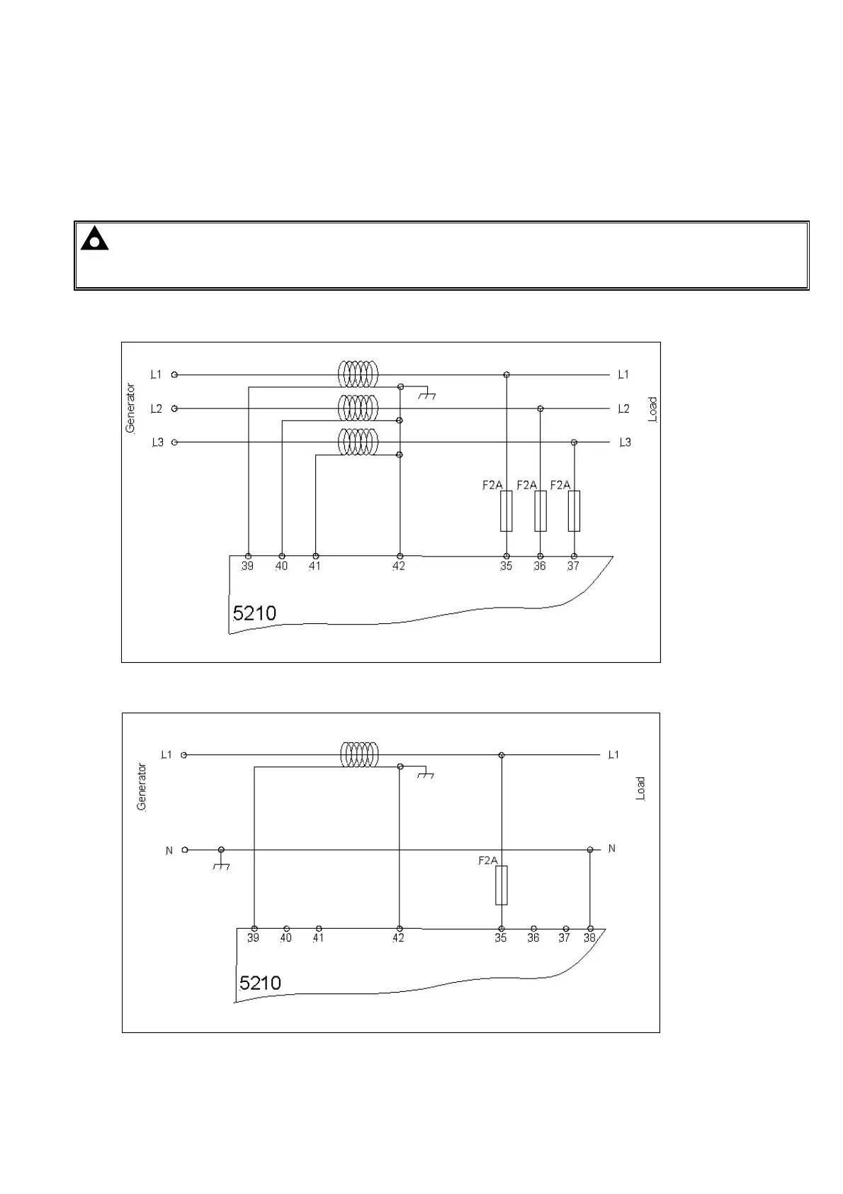
16.1.1 3 PHASE, 3 WIRE
The alternator is 3 phase delta connected. Phases are separated by 120°
16.1.2 1 PHASE, 2 WIRE
Single phase alternator with neutral conductor.
CALL US TODAY
1-888-POWER-58
REQUEST A QUOTE
parts@genpowerusa.com
SHOP ONLINE
www.genpowerusa.com