DSE Model 5210 Automatic Start Engine Management and Instrumentation System Operators Manual
40 057-011 5210 OPERATING MANUAL ISSUE 5.1 18/06/2007 AM
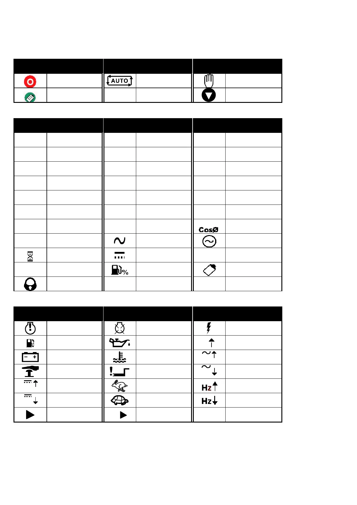
15 ICONS AND LCD IDENTIFICATION
15.1 PUSH BUTTONS
Display Description Display Description Display Description
Stop/Reset
Auto mode
Manual mode
Configure / log
I
Start (when in
manual mode)
Scroll
15.2 STATUS / MEASUREMENT UNITS
Display Description Display Description Display Description
L1
Phase
L2
Phase
L3
Phase
L1- N
Phase - Neutral
L2- N
Phase - Neutral
L3- N
Phase -Neutral
L1- L2
Phase - Phase
L2- L3
Phase - Phase
L3- L1
Phase - Phase
BAR
Pressure
KPa
KPa Oil Pressure
Units
PSI
Pressure
V
Voltage
o
F
Temperature
Hz
Frequency
A
Amperes
o
C
Temperature
RPM
Speed
kW
KiloWatts
kVA
Apparent power
KW divided by
kVA
¤
Hours Run
AC
Generator
Timer in progress
DC
)
Factory (load)
#
Configuration
mode active
Fuel level Event log
Panel locked by
configurable input
15.3 ALARM INDICATIONS
Display Description Display Description Display Description
Warning Alarm
Shutdown Alarm
Electrical Trip
Fuel
Low Oil Pressure
High Current
Warning
Charge Fail
High Coolant
Temperature
V
Over Voltage (AC)
Emergency Stop
Fail to start (Over-
crank)
V
Under Voltage
(AC)
V
Over Voltage (DC)
Over-speed
Over frequency
V
Under Voltage
(DC)
Under-speed
Under frequency
Auxiliary
Indication
!
Auxiliary Alarm
(Warning or Shutdown)
CALL US TODAY
1-888-POWER-58
REQUEST A QUOTE
parts@genpowerusa.com
SHOP ONLINE
www.genpowerusa.com