Do you have a question about the DSEGenset DSE8610 and is the answer not in the manual?
Provides guidance for installing the DSE8610 module.
Details connector types, cable sizes, and pin assignments for the module.
Specifies voltage, current, and protection for the module's power input.
Describes how the module senses generator and bus voltage and frequency.
Lists available communication ports like USB, RS232, RS485, CAN, and Ethernet.
Provides physical dimensions and panel cutout details for module installation.
Explains the function of each terminal for DC supply, fuel, start, sensors, and outputs.
Illustrates common wiring configurations for generator systems.
Details wiring for different AC topologies like single and two-phase systems.
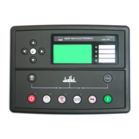
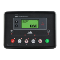
Overview of the module's front panel, display, and buttons.
Explains how to navigate and view system parameters on the LCD display.
Details the function of each button on the module's front panel.
Describes how to stop the engine and the module's behavior in this mode.
Explains how the generator operates automatically with minimal user intervention.
Details how to manually start, stop, and control the generator.
Explains the sequence of operations for dead bus synchronisation.
Lists the necessary hardware for implementing dead bus synchronisation.
Explains how to disable shutdown/trip alarms for specific operational needs.
Lists and describes non-critical warning alarm conditions and their reasons.
Lists and describes critical shutdown alarm conditions and their reasons.
Details the overcurrent protection, including warning and IDMT trip curves.
Explains short circuit and earth fault protection mechanisms and tripping curves.
Describes how scheduled runs operate when the module is in AUTO mode.
Guides the user on how to access and use the front panel editor for parameters.
Explains how to access the configuration editor while the engine is running.
Lists essential checks to perform before starting the system for the first time.
Checks the engine's control systems (AVR, Governor) for synchronisation.
Verifies CT installation and phasing for accurate metering.
Ensures proper communication between modules for synchronisation.
Performs checks like phase wiring and sync scope for safe synchronisation.
Details how to order replacement connector plugs for the DSE8600 module.
Describes DSE's DSENet expansion modules and their connection.
Provides guidance on the proper disposal of electronic equipment.
| Display | LCD |
|---|---|
| Storage Temperature Range | -40 °C to +85 °C |
| Maximum Generator CT | 5 A |
| Protection Rating | IP65 |
| Battery Charging Current | 1 A |
| Input Voltage | 8 - 35 V DC |
| Communication Ports | RS232, RS485, USB |
| Alternator Input Range | 0 - 300 V AC |
| Maximum Generator VT | 300V AC |
| Engine Start Outputs | 2 |
| Analog Inputs | 4 |