Specifications
9
3 SPECIFICATIONS
3.1 TERMINAL SPECIFICATION
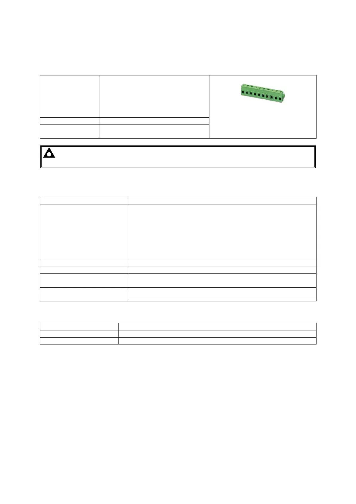
Connection type Two part connector.
• Male part fitted to module
• Female part supplied in
module packing case - Screw
terminal, rising clamp, no
internal spring.
Example showing cable entry and
screw terminals of a 10 way
connector
Minimum cable size 0.5mm² (AWG 24)
Maximum cable
size
2.5mm² (AWG 10)
NOTE: For purchasing additional connector plugs from DSE, please see the section
entitled Maintenance, Spares, Repair and Servicing elsewhere in this document.
3.2 POWER SUPPLY REQUIREMENTS
Minimum supply voltage 8V continuous
Cranking dropouts Able to survive 0V for 50mS providing the supply was at least 10V
before the dropout and recovers to 5V afterwards.
This is more than sufficient to allow the module to operate during
engine cranking where the battery supply often falls as low as 4V (on
a 12V system!)
This is achieved without the need for internal batteries or other
external requirements.
Maximum supply voltage 35V continuous (60V protection for surges)
Reverse polarity protection -35V continuous
Maximum operating current
300mA at 24V
600mA at 12V
Maximum standby current
190mA at 24V
390mA at 12V
3.2.1 PLANT SUPPLY INSTRUMENTATION DISPLAY
Range 0V-70V DC (note Maximum continuous operating voltage of 35V DC)
Resolution 0.1V
Accuracy ±1% full scale (±0.7V)
 Loading...