E2 158004.B00
E.2 EXPANSION BUS CONNECTORS
The PC/104 bus connectors J1 and J2 provide the ISA bus compatible signals. They
have pin assignments that conform to the PC/104 bus specification V2.3. The pin
assignments for these connectors are shown in Table E4 and E3 respectively. The
PC/104-Plus connector J3 provides the PCI compatible signals. The pin assignments
for this connector are shown in Table E5.
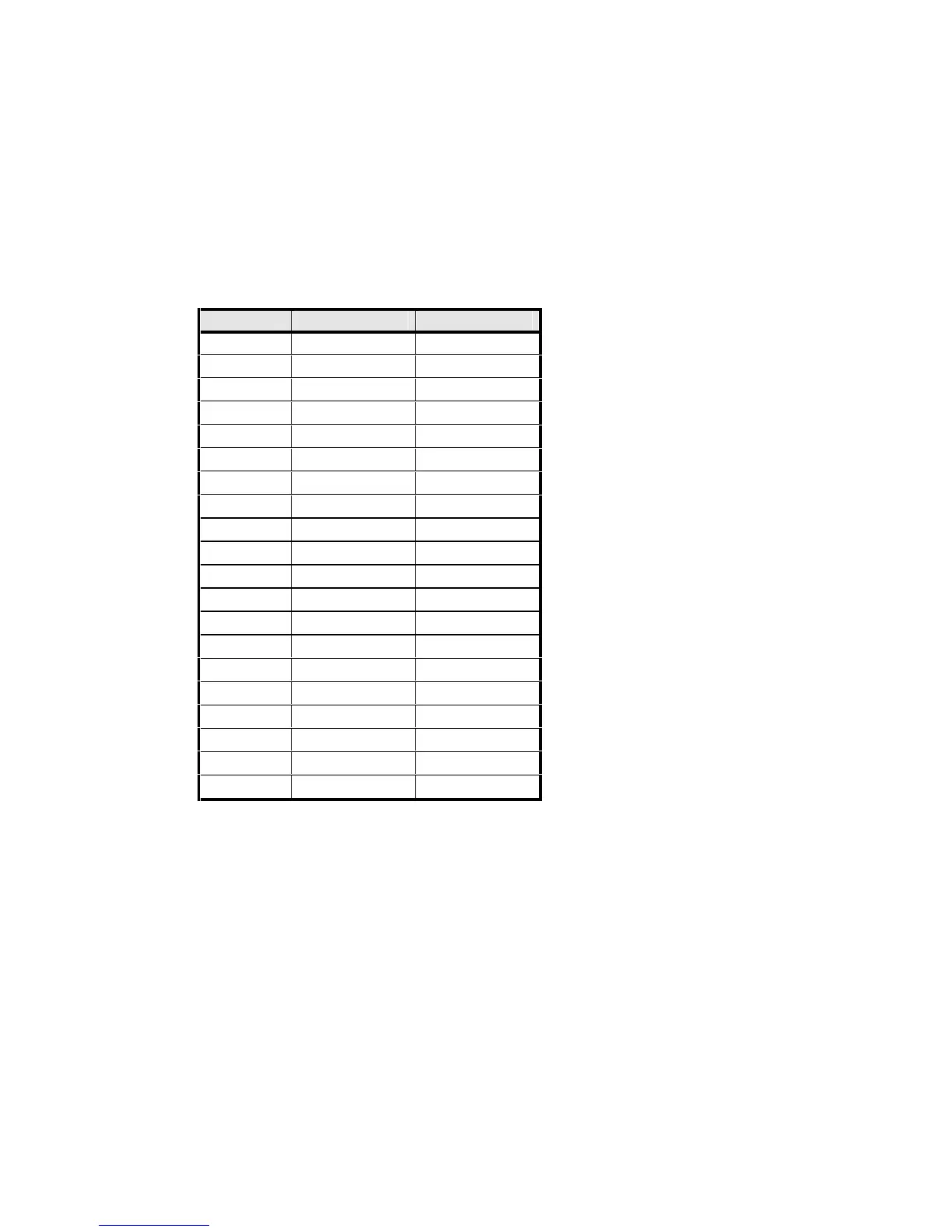
PIN J2 ROW C J2 ROW D
0 0V 0V
1 /SBHE /MEMCS16
2 SA23 /IOCS16
3 SA22 IRQ10
4 SA21 IRQ11
5 SA20 IRQ12
6 SA19 IRQ15
7 SA18 IRQ14
8 SA17 /DACK0
9 /MEMR DREQ0
10 /MEMW /DACK5
11 SD8 DRQ5
12 SD9 /DACK6
13 SD10 DRQ6
14 SD11 /DACK7
15 SD12 DRQ7
16 SD13 +5V
17 SD14 /MASTER *
18 SD15 0V
19 (KEY) 0V
NOTES: * This connection is not implemented on the TP400.
TABLE E3 - PC/104 J2 PIN ASSIGNMENTS
Pins 0 and 19 of the J2 connector are marked on the PCB silk-screen with a “0” and
“19” respectively, and rows C and D are also marked.