20 158004.B00
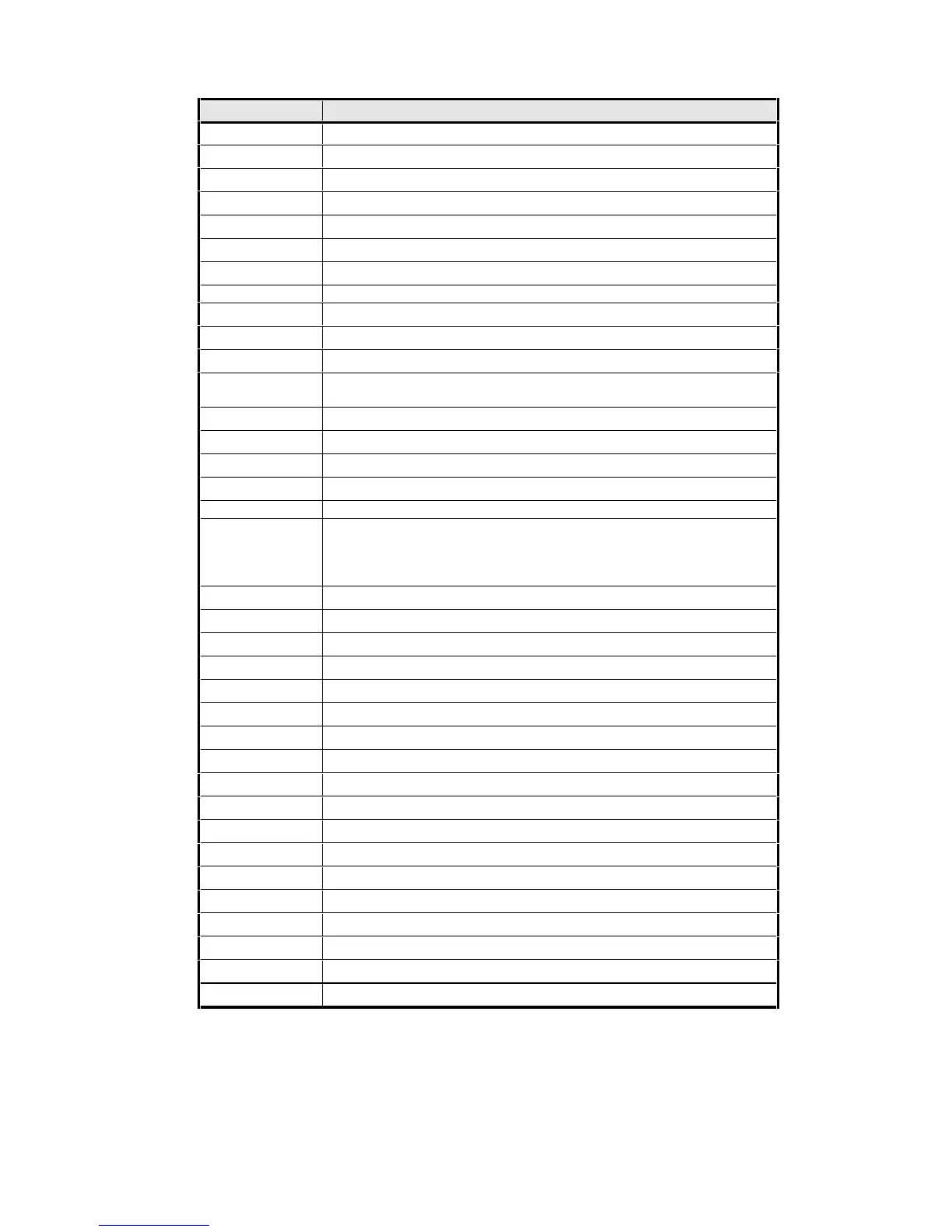
ADDRESS I/O FUNCTION
00 - 0F DMA Controller in Geode GX1
20 - 21 Interrupt controller in Geode GX1
22 - 23 Geode GX1 Processor Configuration Registers
2E - 2F Super I/O Chip Configuration Registers
40 - 43 Timer Unit in Geode GX1
60 and 64 Keyboard controller in Super I/O chip.
61 Port B Control/Status Port in Geode GX1
70 - 71 Real-Time Clock in Super I/O chip and NMI enable in Geode GX1.
80 - 8F DMA Page Registers in Geode GX1
92 Port A System Control Port in Geode GX1
A0 - A1 Interrupt Control/Status Reg. in Geode GX1
C0 - DE (Even
addresses only)
DMA Controller in Geode GX1
E0 - E7 Utility Register in Super I/O Chip
F0 - F1 Coprocessor Error Registers in Geode GX1
102 Enable Register in 65550
1F0 - 1F7 IDE disk controller
200 - 201 Reserved for Game Port
220 - 22F, or
240 - 24F, or
260 - 26F, or
280 - 28F
Sound card compatibility registers, if enabled. One of these addresses
is selected.
2E8 - 2EF COM4: in extra UART chip.
2F8 - 2FF COM2: Serial Port in Super I/O chip.
330 - 38B Sound card FM registers.
378 - 37A Parallel Port in Super I/O chip.
3B4 - 3B5 VGA Register in Geode GX1 (monochrome modes).
3BA VGA Register in Geode GX1 (monochrome modes).
3C0 - 3CF VGA registers in Geode GX1.
3D4 - 3D5 VGA Register in Geode GX1 (colour modes).
3DA VGA Register in Geode GX1 (colour modes).
3E8 - 3EF COM3: Serial Port in extra UART chip.
3F0 - 3F7 Floppy Disk Controller
3F8 - 3FF COM1: Serial Port in Super I/O chip.
481 - 48B DMA high page registers.
4D0 - 4D1 IRQ edge/level select registers.
CF8 - CFF PCI Configuration Registers
121C - 121F ACPI Timer Count Register in Geode GX1
AC00 - AC8F ACPI Registers
F800 – F8FF Typical address range for DP83815 Ethernet chip
TABLE 3 - ON-BOARD I/O DEVICES