158004.B00 E11
E.9 IDE CONNECTOR
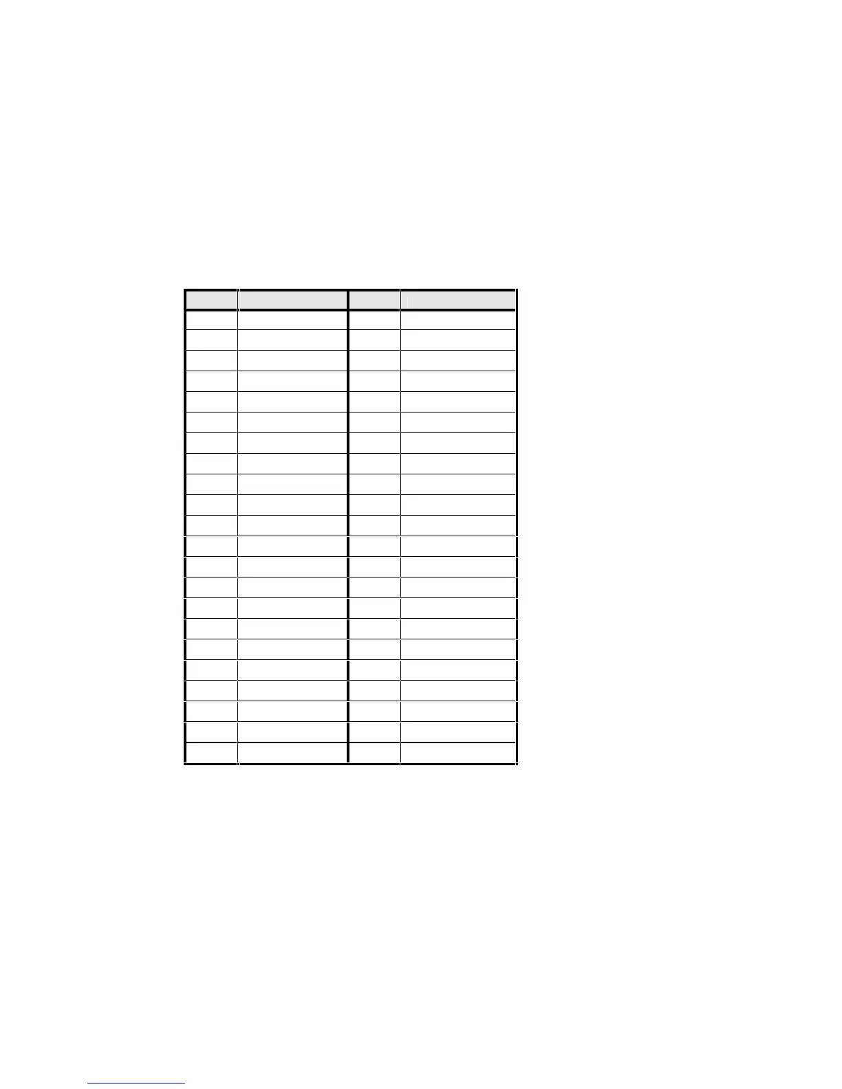
The IDE drive is connected through J100, a straight 2mm pitch 44-way connector. Pin
assignments follow.
Pin 1 of the J100 connector can be identified by looking at the silk-screen legend on
the TP400 PCB. A ’1’ symbol is placed close to pin 1. All odd numbered pins are in
one row and all even numbered pins are in the other row.
PIN SIGNAL PIN SIGNAL
1 /RESET 2 GND
3 ID7 4 ID8
5 ID6 6 ID9
7 ID5 8 ID10
9 ID4 10 ID11
11 ID3 12 ID12
13 ID2 14 ID13
15 ID1 16 ID14
17 ID0 18 ID15
19 GND 20 N/C
21 DREQ 22 GND
23 /IOW 24 GND
25 /IOR 26 GND
27 IOCHRDY 28 GND
29 /DACK 30 GND
31 IRQ14 32 /IOCS16 *
33 A1 34 To LK114 *
35 A0 36 A2
37 /CS0 38 /CS1
39 N/C 40 GND
41 VCC 42 VCC
43 GND 44 VCC
Notes:
Pin 32 is not connected to the Geode GX1 chip set. It is pulled to GND through a
330R resistor.
Pin 34 is /PDIAG. It can be connected to GND or not on the TP400. See description
of LK114.
TABLE E14 - J101 IDE CONNECTOR PIN ASSIGNMENTS