158004.B00 E7
E.4 COM3, COM4 SERIAL PORT CONNECTOR
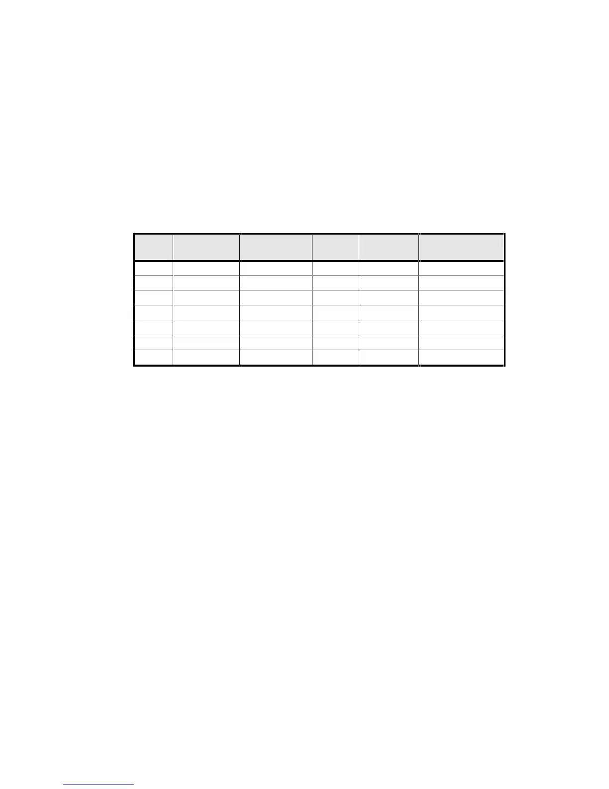
Connector J5 is a 14-way pin header adjacent to J4. It carries the COM3 and COM4
serial port signals. The signals are arranged so that a ribbon cable from J5 can easily
crimp onto a 9-pin IDC D-type connector for COM3.
Pin 1 of the J5 connector can be identified by looking at the J5 silk-screen box that
surrounds the J5 connector on the TP400. A “2” is located close to the pin 1 end of J5
and a “13” is placed close to the pin 14 end. All odd numbered pins are in one row
and all even numbered pins are in the other row.
J5
PIN
SIGNAL D-TYPE PIN J5 PIN SIGNAL D-TYPE PIN
1 N/C - 2 /PME -
3 GND 5 4 RI2 9
5 DTR3 4 6 CTS3 8
7 TXD3 3 8 RTS3 7
9 RXD3 2 10 DSR3 6
11 DCD3 1 12 VCC -
13 /TXD4 - 14 /RXD4
TABLE E8 - J5 COM3, COM4 CONNECTOR PIN ASSIGNMENTS
E.5 AUDIO, A/D CONVERTOR AND CRT CONNECTOR
Connector J6 is a 16-pin right angle pin header. It carries the audio or analog to
digital converter signals and the signals for a VGA CRT display. Also included on the
connector is the Geode GX1 suspend/resume signal.
Note that either the audio signals or the A/D converter signals are brought to the
connector. Thus some pins are given one function in the columns marked "(AUDIO)"
and other functions in the columns marked "(A/D)". Appendix B describes how the
options are selected.
The VGA CRT display signals are usually connected to a 15-pin high density D-type
connector. Pin assignments for this connector are also given in the table.
Pin 1 of the J6 connector can be identified by looking at the J6 silk-screen box that
surrounds the J6 connector on the TP400. A "1" and “2” are located close to pins 1
and 2. All odd numbered pins are in one row and all even numbered pins are in the
other row.