158004.B00 F3
F.4 TFTIF CONNECTOR AND SOLDER LINKS
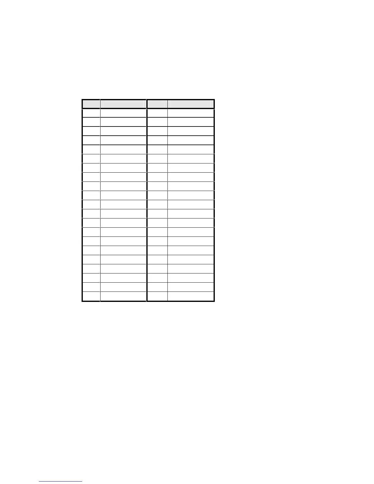
Table F2 gives the pin assignments of the TFTIF display connector.
PIN LCD SIGNAL PIN LCD SIGNAL
1 GND 2 SHFCLK
3 GND 4 GND
5 HSYNC 6 VSYNC
7 GND 8 RED 0
9 RED 1 10 RED 2
11 RED 3 12 RED 4
13 RED 5 14 GND
15 GND 16 GND
17 GREEN 0 18 GREEN 1
19 GREEN 2 20 GREEN 3
21 GREEN 4 22 GREEN 5
23 GND 24 GND
25 GND 26 BLUE 0
27 BLUE 1 28 BLUE 2
29 BLUE 3 30 BLUE 4
31 BLUE 5 32 GND
33 GND 34 GND
35 ENABLE 36 VCC
37 VCC 38 N/C
39 N/C 40 GND
41 GND -
TABLE F2 - TFTIF DISPLAY PIN ASSIGNMENTS
The TFTIF has one solder link, LK1. This can be set to one of two positions. The
position marked "5" is for 5V LCD panel. The position marked "3.3" is for 3.3V
displays. You may need to change the solder link to match your display. The LG
Electronics LP121S1 uses +3.3V.