42
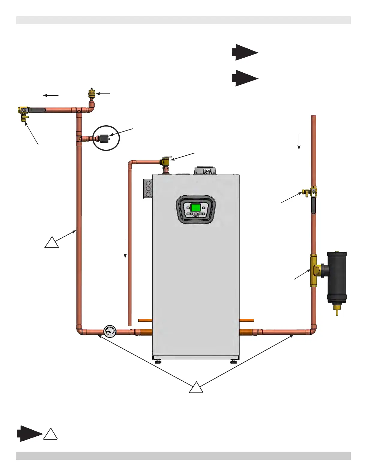
PIPING DIAGRAM - LWCO LOCATION
LOW WATER CUTOFF
Air Vent
Supply
Gas
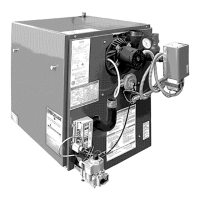
Boiler
Safety Relief
Valve
Position LWCO Above
Top of Boiler
1
DO NOT PLACE ISOLATION VALVE
BEFORE TEE OR LWCO.
Note
*To Drain
* Check Local Codes for
Maximum Distance to
Floor.
Arrange piping to prevent water
dripping onto boiler.
1
Return
Magnetic
Dirt
Separator
Purge Valve
Purge Valve
Illustrations are meant to show
system piping concept only. Installer
is responsible for all equipment and
detailing required by authority having
jurisdiction.
1
Note
Note
PN 240012875 REV. B [07/01/2021]