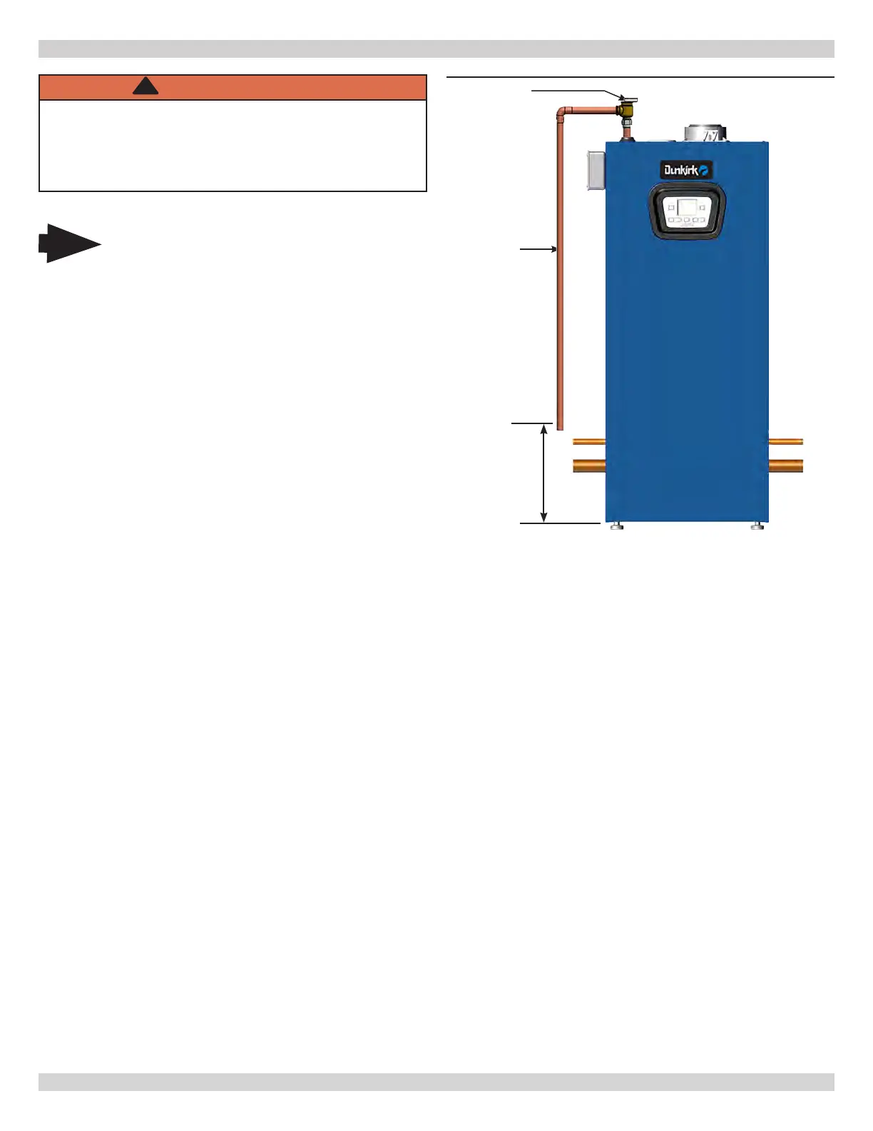
Check Local Check Local
Codes For Codes For
Maximum Maximum
Distance To FloorDistance To Floor
Safety Relief
Valve
Do not use
plastic pipe see
Warning above.
FIGURE 6-1 Safety Relief Valve
31
6.3 Safety Relief Valve and Air Vent
•
provided with boiler. See Figure 6-1.
• Install safety relief valve with spindle in vertical
position.
•
safety relief valve.
• Install discharge piping from safety relief valve.
Do not use plastic pipe.
• Use ¾" or larger pipe.
• Use pipe suitable for temperatures of 375°F
(191°C) or greater. Do not use plastic pipe on
safety relief valve.
• Individual boiler discharge piping shall be
independent of other discharge piping.
• Size and arrange discharge piping to avoid
reducing safety relief valve relieving capacity
below minimum relief valve capacity stated on
rating plate.
• Run pipe as short and straight as possible to
location protecting user from scalding and
properly drain piping.
• Install union, if used, close to safety relief valve
outlet.
• Install elbow(s), if used, close to safety relief
valve outlet and downstream of union (if used).
• Terminate pipe with plain end (not threaded).
WARNING
Burn and scald hazard. Safety relief valve could
discharge steam or hot water during operation.
Use pipe suitable for temperatures of 375°F
(191°C) or greater. DO NOT use plastic pipe.
Install discharge piping per these instructions.
!
6 - HYDRONIC PIPING
6.4 Trim Piping
• Temperature - Pressure Gauge. Install temperature
pressure gauge using tee and bushing provided in
near boiler piping on supply side. See Figure 6-2.
• Some boiler models may have integral drain valve
located inside jacket directly underneath pump.
Install external drain valve as required.
6.5 System Piping
• Ensure plugs are removed from boiler water
connections.
• See Figure 6-5 for basic system piping
•
prevention device.
• Single boiler system. See Figures 6-2, 6-5, for
general guidance. Additional considerations:
• Boiler control only supports integrated pump.
Installer responsible for integration of multiple
external control.
• Boiler control allows domestic hot water
prioritization.
•
•
• Manufacturer recommends installing an isolation
and purge valve to use during commissioning to
ensure the boiler does not shut down due to over-
• Do not install isolation valve between boiler and any
• If soldering piping to boiler, avoid over heating and
damaging seals and gaskets.
• Connect system valve pipe work to the boiler.
• Route pressure relief valve discharge piping to the
See Figure 6-1.
• Verify all drain valves are closed.
When installing safety relief valve it must
be installed in a vertical position with
spindle at top.
Note
240013375 REV A, [07/01/2021]