60
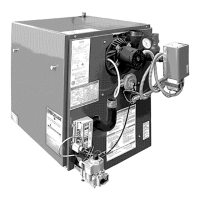
11.6 Hydraulic Unit (DHW)
For special areas, where water is harder than 200 ppm
or 12 grains/ gallon, install polyphosphate dispenser or
equivalent treatment system, compliant with current
regulations.
LEGEND
A DHW Exchanger Screw
B DHW Priority Sensor
C Boiler/System Drain Tap
D
Controlled Fast Fill
E DHW Temperature NTC Probe
F
G DHW Cold Inlet
H DHW Outlet
11.7 Cleaning The Cold Water Filter
hydraulic assembly (B). To clean:
• Drain domestic hot water system. (C - 115 & 150)
•
• Remove nut on DHW priority sensor unit using 18
mm wrench. (B)
•
• Remove any impurities.
11.8 Final Commissioning
• Allow heating system to heat. Balance the system
supply and return pipes at the boiler.
• Check system for proper volume and pressure. See
page 4 for acceptable volume and pressure.
•
•
heating return and supply water isolating valves.
• Repressurize the system.
11.9 Final Assembly
• Place front jacket in position over boiler. Secure in
position at top using screws previously removed.
• If boiler is to be left in service with the User, set
controls and room thermostat.
• If boiler is not to be handed over immediately,
supply.
• If there is possibility of boiler being left during frost
conditions drain boiler and system. See section
11.3 Component Replacement and Cleaning.
Manufacturer recommends attaching a label to the
boiler drawing attention to the fact that the system
has been drained.
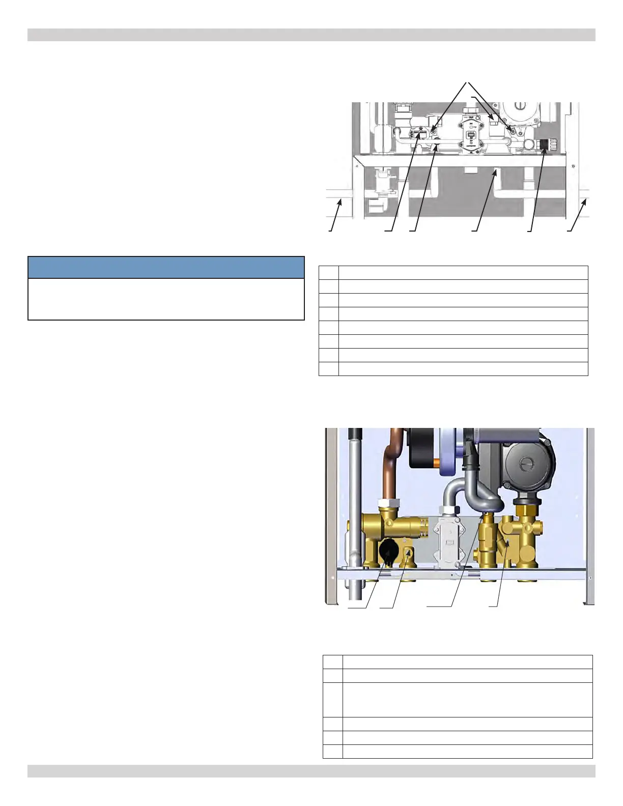
Model DCCF-115 & 150
Hydraulic Assembly (Combi-150)
NOTICE
When replacing and/or cleaning “O-rings” on
hydraulic assembly (DHW), use only Molykote
111 as a lubricant, not oil or grease.
11 - GENERAL MAINTENANCE AND CLEANING
HH GG
LEGEND
A DHW Exchanger Fixing Screw
B DHW Priority Sensor With Filter
C
Boiler/System Drain Tap (150 Unit Only)
(C-1 & C-2: Access To Tap C - Bottom Of
Boiler)
D Boiler / System Filling Tap (150 Unit Only)
E DHW Temperature NTC Probe
F
Model DCCF-205
B
A
Hydraulic Assembly (B)
F
E
FF EE DD CC
AA
BB
240013375 REV A, [07/01/2021]