16
NOTE: Greater clearances for access should supersede
Minimum ClearanceMinimum Clearance
17 ¾ in. [450 mm ] 17 ¾ in. [450 mm ]
From Front of Boiler From Front of Boiler
13.58 in /
345.00 mm
1212 inin
[305 mm][305 mm]
17 in
[450 mm]
8 ⅝in [220 mm]
40 in
[1.02 m]
100, 115,
125, & 150
13 in
[345 mm]
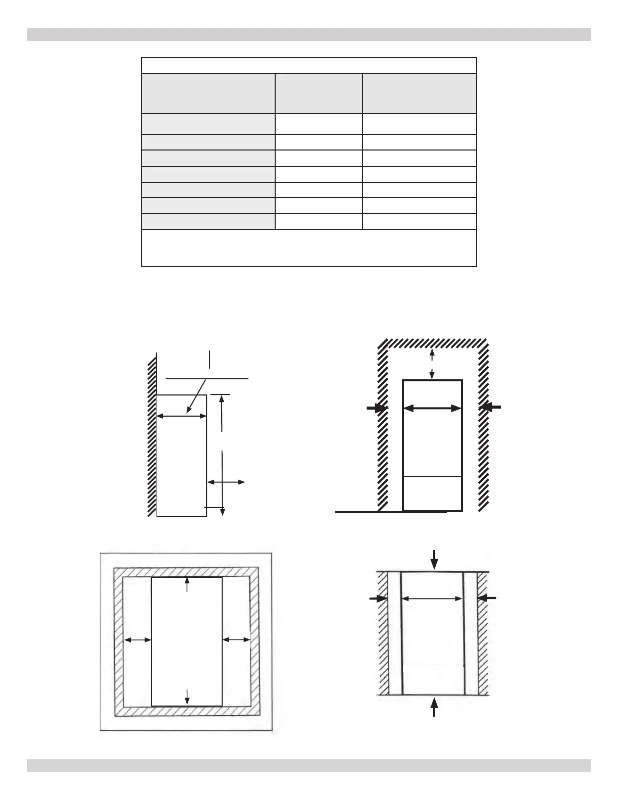
4.3 Clearances
1 1 inin
[45 mm] [45 mm]
Left Side View of Boiler Front View of Boiler
Service Clearances
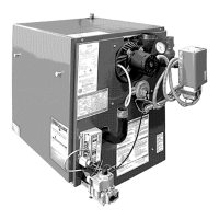
4 - LOCATING BOILER
1 in
[45 mm
]
17in
Top ViewTop View
BackBack
Closet Installation
0 in /0 mm between Back of Unit and wall 0 in /0 mm between Back of Unit and wall
1 in
[45 mm]
1in
[45 mm]
1in
[45 mm]
[450 mm]
Front View of Boiler
0 in
[0 mm]
0 in
[0 mm]
Top View
0 in
[0 mm]
0 in
[0 mm]
Combustible Clearances
TABLE 1: BOILER CLEARANCES
Dimension
Combustible
Materials
(1)
Manufacturer
Recommended for
Service
(1)(2)
Top
0" (0 cm) 8-5/8" (220 mm)
Left Side
1-3/4" (45 mm) 12" (305 mm)
Right Side
1-3/4" (45 mm) 1-3/4" (45 mm)
Front
0" (0 mm)
17-3/4"(450 mm)
Back
0" (0 mm)
0" (0 mm)
Bottom
0" (0 mm)
0"(0 mm)
Combustion Air/Vent piping
0" (0 mm) 6" (160 mm)
(1)
Required distances measured from boiler jacket.
(2)
Service, proper operation clearance recommendation.
* Allowance for piping and venting not included.
165 & 205
23 ½ in
[597 mm]
240013375 REV A, [07/01/2021]