(See Figure 6-3 for detail)
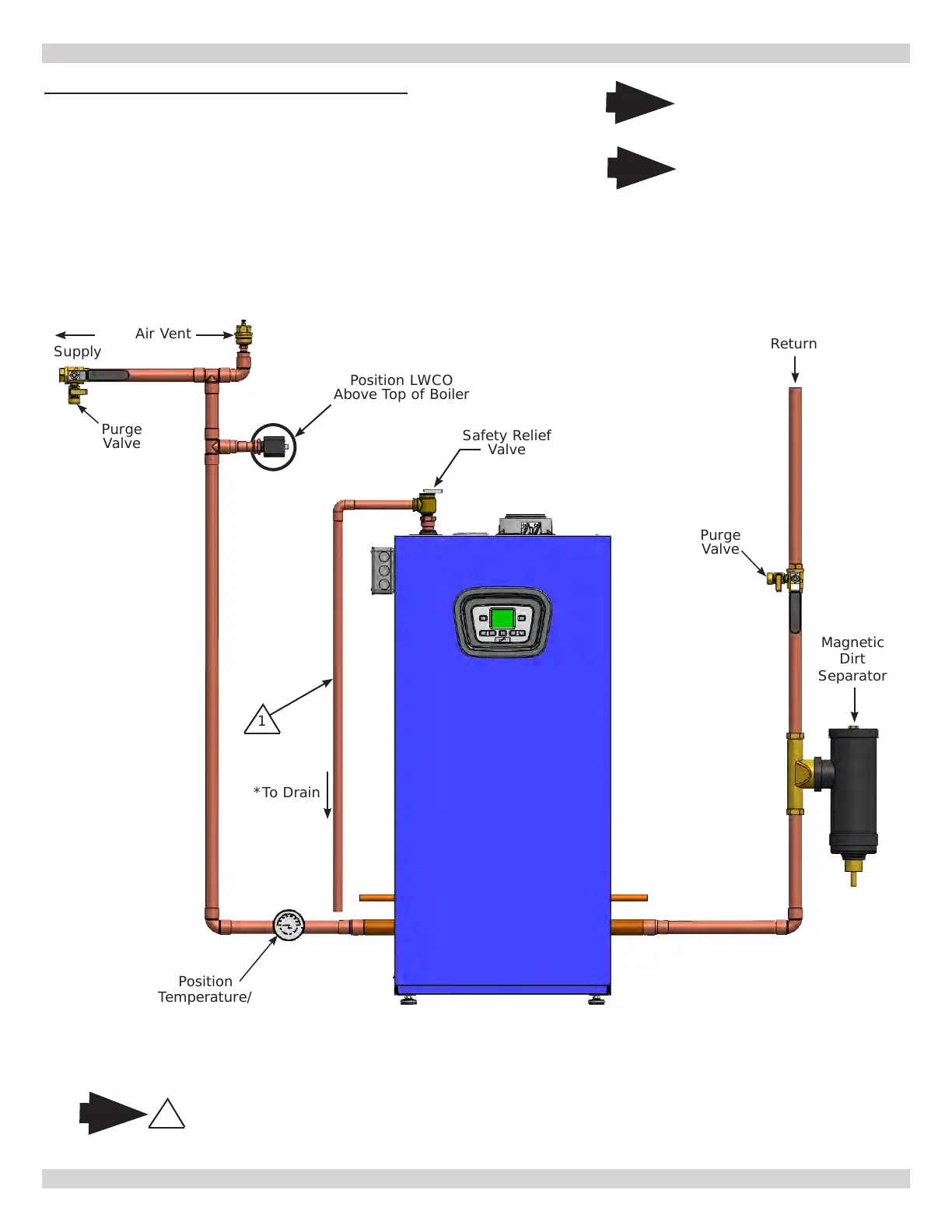
Air Vent
Supply
Safety Relief
Valve
Position LWCO
Above Top of Boiler
1
DO NOT PLACE ISOLATION VALVE
BEFORE TEE OR LWCO.
Note
*To Drain
* Check Local
Codes for Maximum
Distance to Floor.
Arrange piping to prevent
water dripping onto boiler.
1
Return
Purge
Valve
Magnetic
Dirt
Separator
Position
Temperature/
Pressure Gauge on
CH System Supply
Side of Boiler.
Purge
Valve
Note
Illustrations are meant
to show system piping
concept only. Installer
is responsible for all
equipment and detailing
required by authority
having jurisdiction.
Note
32
FIGURE 6-2 - Piping Diagram - LWCO Location
6 - HYDRONIC PIPING
240013375 REV A, [07/01/2021]