27
6 - COMBUSTION AIR AND VENT PIPING
Exhaust and combustion air intake are located in same general
location and are of equal length.
Twin Pipe Maximum Vent Lengths
Terminating in same location
125/150 165/205
3" [80 mm] 3" [80 mm] 2" [50 mm]
49 ft 100 ft 85 ft
Single Wall Elbows - Equivalent Length
3" 2"
45° bend 0.82 ft [0.25 m] 3 ft. [0.91m]
90° bend 1.64 ft [0.50 m] 5 ft [1.5 m]
Note: Twin Pipe Common Atmospheric Zone termination
can be run horizontal or vertical
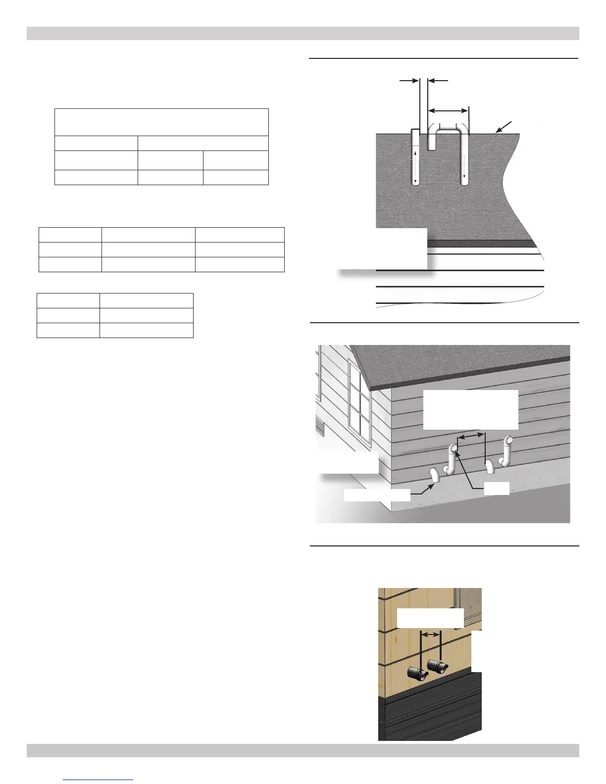
FIGURE 6-11-Twin Pipe Roof Vent
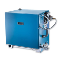
FIGURE 6-12 -Twin Pipe Side Wall Vent (Multiple
Appliances)
Vent
12" (305mm) Min.
Separation
Manufacturer Recommends
Greater Separation
Combustion Air
15"
(381mm)
Max.
Vent
Combustion
Air
12" (305mm) US,
18" (458mm) Canada
Min. Above
Anticipated Snow Line
Roof Line
12" (305mm) Min.
See Grade,
Snow & Ice
FIGURE 6-13 - Horizontal Twin Pipe, Exhaust and
Intake
12" (305mm)
Minimum Separation
Manufacturer
Recommends
Greater Separation
Polyproplene
PVC/CPVC
3"
45° bend 3.5 ft [1 m]
90° bend 5.0 ft [01.50 m]
240011947 REV B, [03/31/2018]