28
6 - COMBUSTION AIR AND VENT PIPING
Roof
Terminations
12" (305mm) Min. horizontal separation
between combustion air intake and vent of
same appliance.
12" (305mm) Min. 84" (2.2m) Max. vertical
separation between combustion air intake
and vent of different appliances.
15" (381mm) Max. horizontal length of
vent.
Min. vent/intake between different
appliances 12" (305mm).
Max. allowable total vertical vent length
with outside exposure is 10 ft.(3.05m).
Abandoned unused masonry chimney may
be used as chaseway for combustion air
and vent. Both combustion air and vent
pipe must exit above top of chimney with
clearances as shown in gure 6-11.
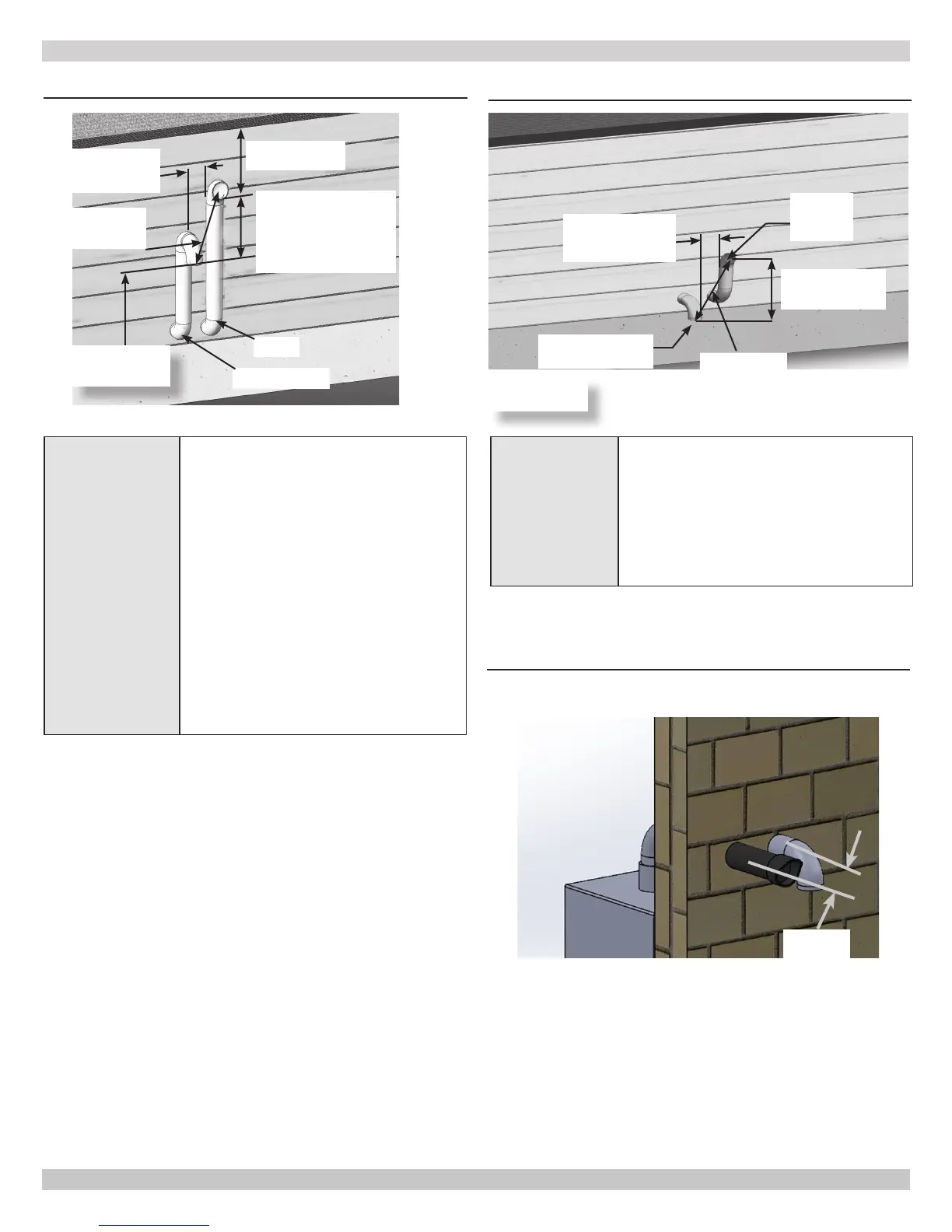
FIGURE 6-14 -Twin Pipe Side Wall Vent
Vent
3" (76mm) Min.
24" (610mm) Max.
Separation
12"(305mm)Min.
From Overhang
12" (305mm) Min.
24" (610mm) Max.
Separation Between
Bottom Of
Combustion Air Intake
And Bottom Of Vent
Combustion Air
Opening
Separation 24"
Min.
Grade, Snow
& Ice
Maintain 12"(305mm) US, 18"(457mm)
Canada clearance above highest anticipated
snow level, 24" (610mm) above roof.
Avoid locations where snow may drift and
block vent and combustion air. Ice or snow
may cause boiler to shut down if vent or
combustion air becomes obstructed.
See Grade,
Snow & Ice
FIGURE 6-15 -Twin Pipe Side Wall with 45° Vent
Vent
45° Elbow
Upward
3" (76mm) Min.
24" (610mm) Max.
Separation
Combustion Air, 90°
Elbow Downward
12" (305mm) Min.
24" (610mm) Max.
Separation
Opening
Separation 24"
Min.
See Grade,
Snow & Ice
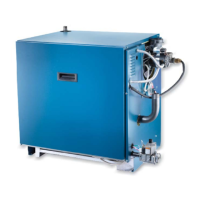
FIGURE 6-16- Single Wall Exhaust Kit and Air Intake
Minimum Distance Center to Center
4
[120mm]
240011947 REV B, [03/31/2018]