UFM2/UBT User Manual
Issue 1.1b July 20 Page 9
NOTE: ENSURE THE WHITE WIRES ARE CORRECTLY ASSOCIATED WITH THE
BLACK & BROWN WIRES. THE BLACK/WHITE TWISTED PAIR IS FITTED WITH A
BLACK SLEEVE TO DISTINGUISH BETWEEN THE BLACK/WHITE AND
BROWN/WHITE PAIRS.
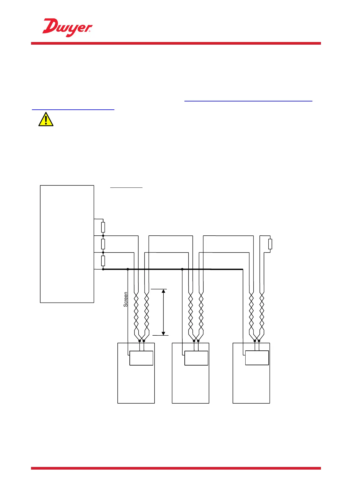
For reliable operation of a Modbus network the cable type and installation must comply with
requirements in the Modbus specification document “MODBUS over Serial Line Specification &
Implementation guide V1.0”.
THIS OUTPUT IS SUITABLE FOR SELV CIRCUITS ONLY.
For full immunity to electrical interference the screen of the power/pulse output cable and Modbus
cable should be connected to Earth.
For full immunity to electrical interference the screen of the power/pulse output cable and Modbus
cable should be connected to Earth.
Figure 9 Example recommended Modbus wiring diagram