UFM2/UBT User Manual
Issue 1.1b July 20 Page 13
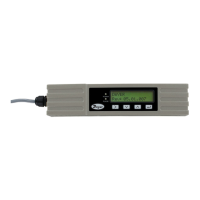
2.4 Adjust Flow Sensor Separation
Using the separation code displayed by the Electronics Module (see page 10), take the Sensor
Assembly and adjust the flow sensor separation accordingly:
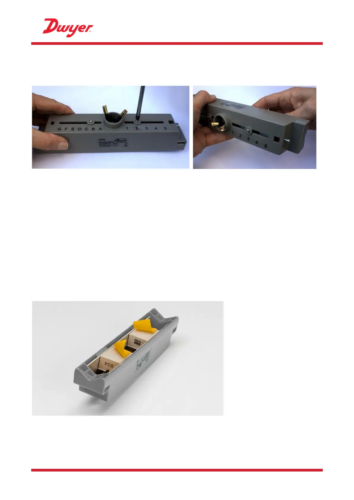
Figure 11 Loosen the flow sensor-holding screws (left); slide to correct position (right)
1. Undo the screws 2-3 turns, sufficiently to loosen the flow sensors and allow sideways
movement. DO NOT fully unfasten or remove the screws at this stage.
2. Slide the flow sensors to the positions indicated on the display (e.g. “D5”).
3. With the flow sensors in the correct positions, tighten the sensor-holding screws so that the
sensors are secure.
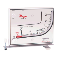
2.5 Apply Gel Pads
1. Apply a gel pad centrally onto the bases of each of the two flow sensors.
2. Remove the covers from the gel pads.
3. Ensure there are no air bubbles between each pad and sensor base.
Figure 12 Applying the gel pads