UFM2/UBT User Manual
Page 8 Issue 1.1b July 20
2.2.2 Pulse Output Connection
The isolated pulse output is provided by a SPNO/SPNC MOSFET relay which has a maximum load
current of 500 mA and maximum load voltage of 24 VAC/VDC.
THIS OUTPUT IS SUITABLE FOR SELV CIRCUITS ONLY.
The pulse output is available at the White and Green wires. Electrically this is a Volt, or potential
free contact and, when selected as a low flow alarm, is configurable NO/NC.
2.2.3 Current Output (UFM2 only, if fitted)
The isolated 4-20 mA is a current source and can drive into a maximum load of 620 Ω.
The 4-20 mA current output is available at the Red and Black wires. The polarities are shown in
Figure 6. The alarm current due to a flow outside the range specified or due to a loss of signal is set
at 3.5mA.
THIS OUTPUT IS SUITABLE FOR SELV CIRCUITS ONLY.
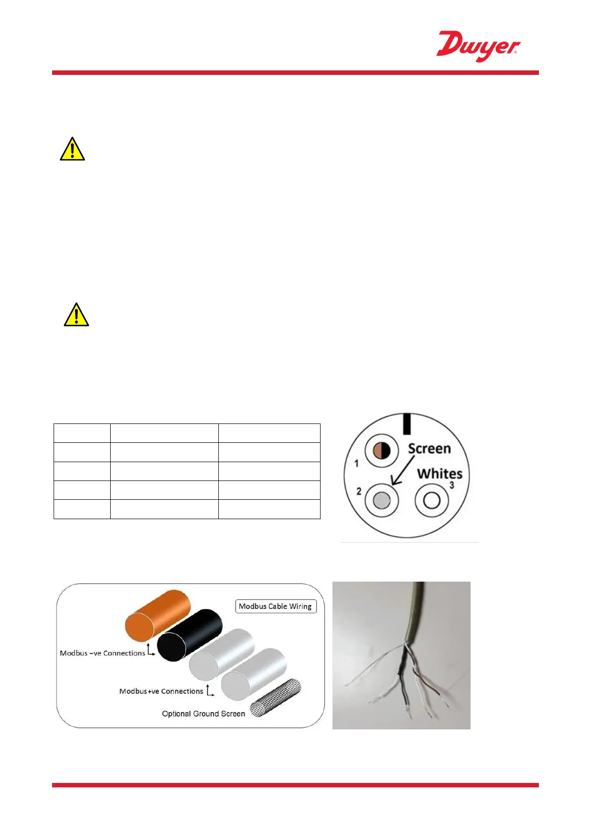
2.2.4 Modbus Connections (if fitted)
A separate 4 core plug-in cable is provided for the Modbus connections.
This plugs into the Electronics Module near the power cable entry.
Figure 7 Modbus Connector Cable Part - Binder 99-9210-00-04 (Front View)
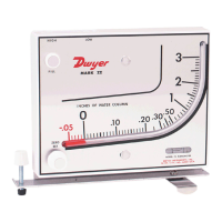
Figure 8 Modbus cable wiring