UFM2/UBT User Manual
Issue 1.1b July 20 Page 17
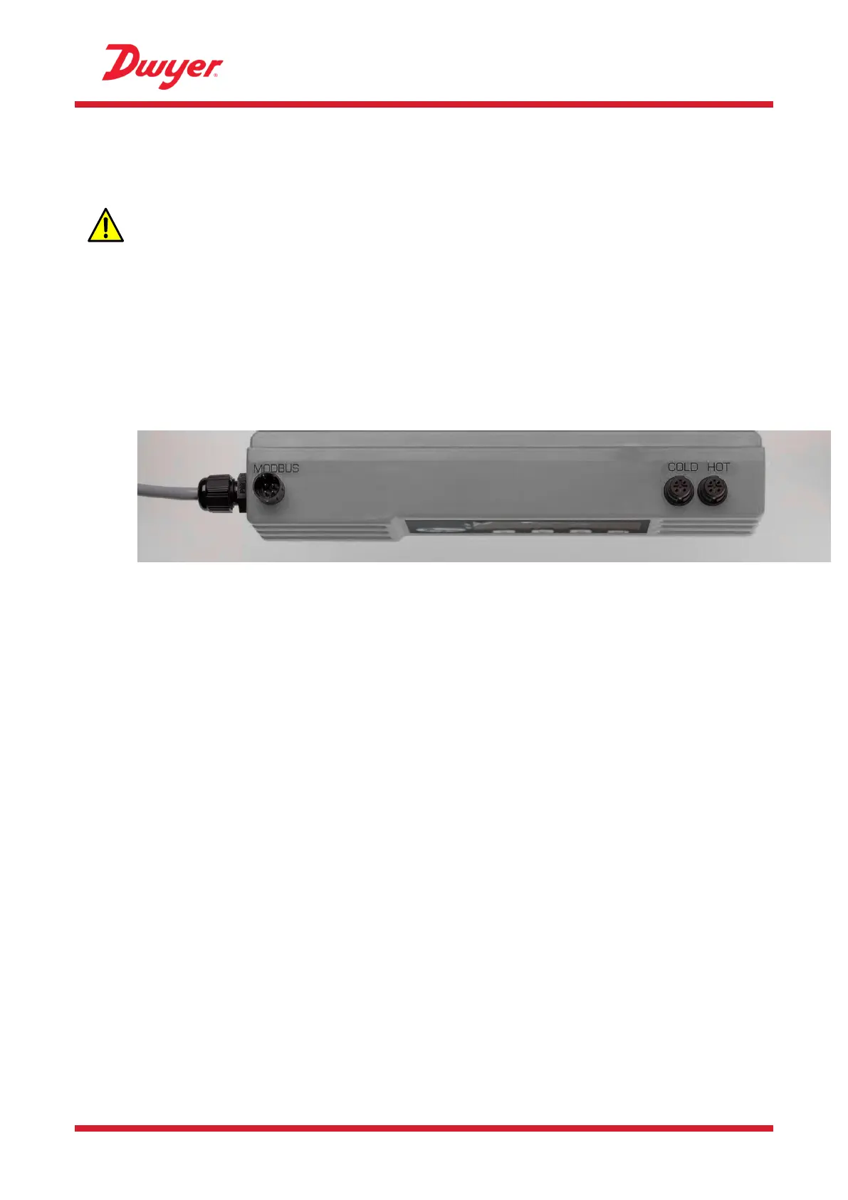
Figure 18 Connecting the Electronics Module
2.9 Attach the Temperature Sensors (UBT Only)
IMPORTANT: THE TEMPERATURE SENSORS MUST BE BALANCED BEFORE
INITIAL USE, USING THE PROCEDURE DESCRIBED BELOW AND USED WITH THE
CABLE LENGTH SUPPLIED. EXTENDING OR SHORTENING THE CABLES WILL
NEGATE THE CALIBRATION OF THE SENSORS.
The temperature sensors must be located at the input and output of the system that is being
monitored. The area of pipe where they are to be attached must be free of grease and any
insulating material. It is recommended that any coating on the pipe is removed so that the sensor
has the best possible thermal contact with the pipe.
The sockets on the Electronics Module are marked Hot and Cold (see Figure 19). This defines the
location of the temperature sensors on installations where heat is being extracted from the system.
Figure 19 Temperature Sensor connectors on the Electronics Module
To ensure an accurate temperature differential:
1. Plug the temperature sensors into the Electronics Module and place them touching each other
for 1 minute.
2. Enter the password controlled menu and scroll to the Calibration sub-menu (see page 20).
3. Press the Enter key until the Zero Temp Offset screen is displayed (see page 25).
4. Select Yes and press the Enter key to display the Attach Sensors screen.
5. Press the Enter key again and wait for instrument to return to the Zero Temp Offset screen.
6. Switch off the power to the Electronics Module.
7. Complete the installation of the temperature sensors. The temperature sensors have a cut out
profile to locate them; they are then anchored using the supplied cable ties. The cable ties
should not be over tightened or the sensors may be damaged. If the sensors are located under
pipe-lagging then ensure this does not put a strain on the sensor cables.
8. Tie down the sensor cables.