29CA 150 M150EN2
2
2
1
56 7 8
34
ELECTRICAL SYSTEM, FUSES
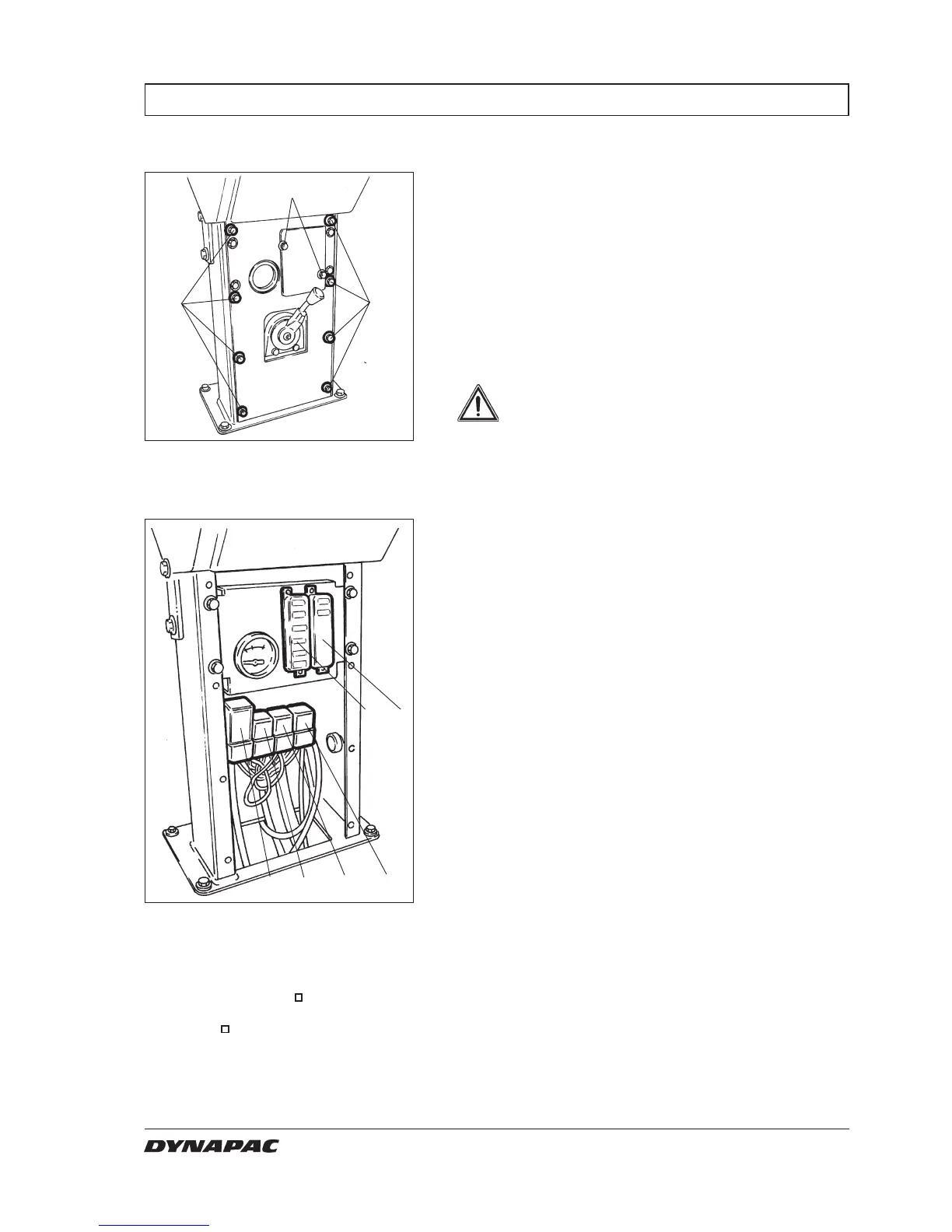
Fig. 42 Instrument panel
3,4. Fuse box
5. VBS relay
6. Main relay
7. Hourmeter relay
8. Lights relay
Fig. 41 Instrument panel
1. Screws (x2)
2. Screws (x8)
Fuses and relays
= Optional
The electrical regulating and control system is
protected by fuses and relays. The number depends on
how much additional equipment the machine is
prepared for.
The two fuse boxes (3, 4) and the relays (5, 6, 7, 8) are
located behind the lower instrument plate, which is
removed by unscrewing the screws (1 and 2).
The machine is equipped with a 12 V electrical system
and an alternator.
Connect the battery to the correct polarity
(– to ground). The cable between battery
and alternator must not be disconnected
when the engine is running.
WARNING