FINAL QUALITY CHECK (QC) CHECKOFF SHEET
DYNATRON SOLARIS
®
PLUS SERIES | SERVICE MANUAL REV. 6 | AUGUST 29, 2017 147
Device Specific Procedure
QC, Assembly, Calibration, and Test
D719 Check Sheet -
1 of 9- DS0408A – REV 1
UPDATED MICROCURRENT, 3WL QC CHANGES AND GENERAL UPDATE
DYNATRON SOLARIS
PLUS
D719
FINAL QUALITY CHECK (QC) CHECKOFF SHEET
Repair____RS____Production____ Software Version__________ (initials or mark)
Refer to Test equipment operation manual and unit operating instructions/ manuals
1
• Verify all keys function, all keys have feedback
• Verify output turns off when STOP is pressed
•
Verify output will time out
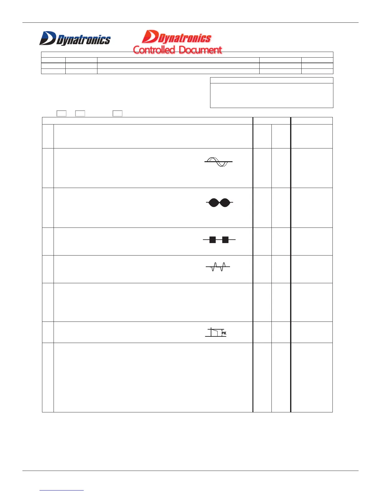
2
INTERFERENTIAL: 42-55 Vpp (
500ohm 10W load intensity 30
a) Static- High/Low (all channels) ± 4 Vpp
b) Target/ Sweep (all channels)
c) Modify Features (mode, time, function, cancel)
d) Verify current limit 50mA maximum with open load
3
500ohm 10W load intensity 30)
a) High/Low (all channels)
b) High/Low alternating (all channels)
c) Modify Features (mode, time, cancel)
d) Verify current limit 50mA maximum with open load
4
RUSSIAN STIM: 42-55 Vpp (
500ohm 10W load intensity 30)
a) One Channel Normal (all channels)
b) Two Channel Reciprocal (channel pairs)
c) Two Channel Co-contraction (channel pairs)
5
500ohm 10W load intensity 30)
a) One Channel Normal (all channels)
b) Two Channel Reciprocal (channel pairs)
c) Two Channel Co-contraction (channel pairs)
6
a) Verify no load, Freq .3Hz, turn off conductance; select Conductance and then
select OFF. At 50 uA +/-4% and at 990 uA +/-1%
b) Verify the polarity changes.
c) Verify conductance.
7
a) No load, set device to 50 V, verify 42-52 V output.
b) Verify that polarity changes.
8
a) No load, Verify DC output, change Pulse Duration to 500. 0-20 mA
b) Verify DC polarity change
c) Verify Hi-Volt output
d) Verify Hi-Volt polarity change
e) Verify micro-current output
f) Verify micro-current polarity change
g) Verify micro-current audible tone
h) Verify UP/DOWN key works
i) Verify ON/OFF key works
j) Verify conductance