EMS Operation
5-2 SkyView SE Pilot’s User Guide - Revision I
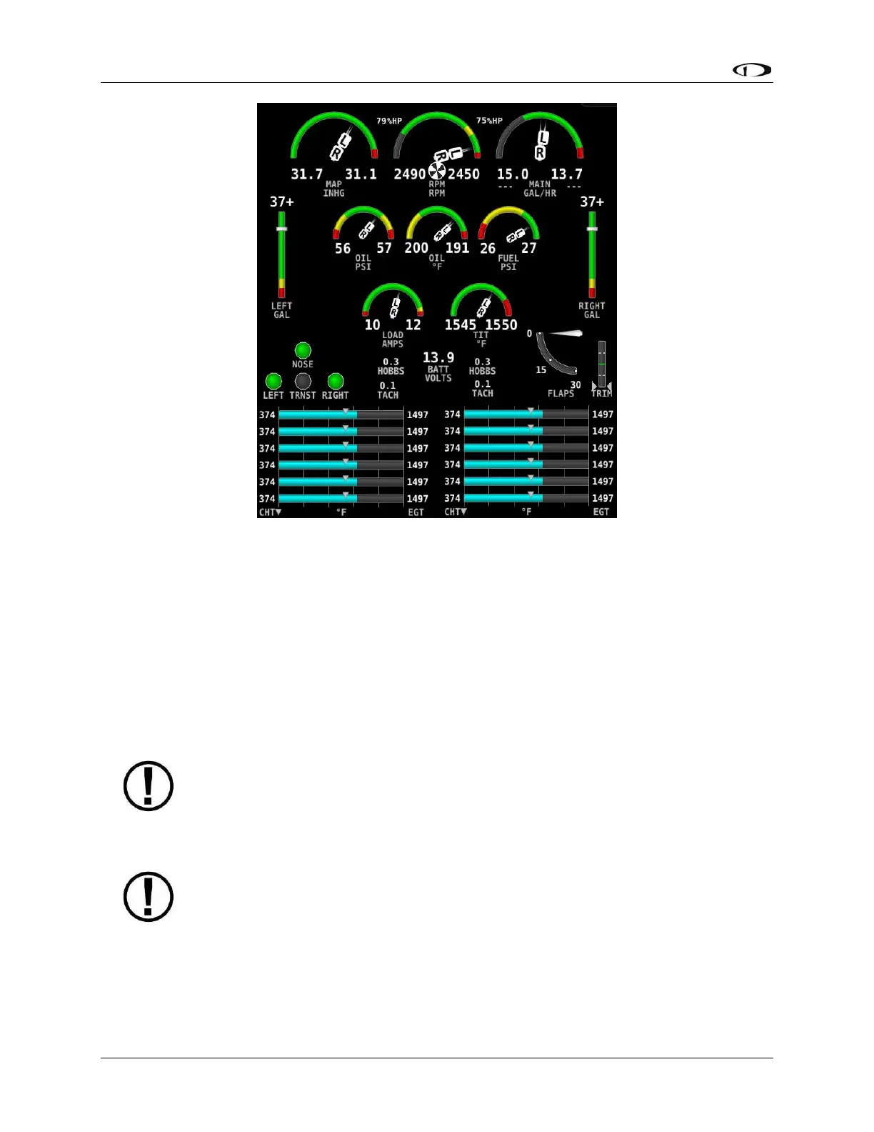
Figure 36 – Example 50% Engine Page for Twin Engine
Its appearance is determined using the Screen Layout Editor under the EMS Setup Menu and
should have been configured during installation. All EMS widgets that have assignable color
ranges, can include: red, yellow, green, black, blue, white, purple, cyan, and orange, for
customization. For more information regarding the Screen Layout Editor, reference the SkyView
Classic / SE / HDX System Installation Guide.
The green markings on pitch/roll/rudder trim indications, if they exist, nominally depict the
take-off position markings as defined during calibration.
Engine warning alerts are only triggered when their respective sensors are
configured as self-clearing or latching alarms. If a sensor’s alarm is configured as
off, no alert will trigger, even if that sensor’s measurement enters a range defined
as red. Reference the SkyView Classic / SE / HDX System Installation Guide for more
information regarding alarm configuration.
Engine parameters only trigger alerts in the Message Notification Area and
Message Window when they enter their “red” ranges. In other words, “yellow”
caution ranges for engine parameters do not trigger alerts. Yellow caution ranges,
however, are visually annunciated via yellow highlighting on the Engine Page.