2388-MANUL-V10.00.00-UTP2 Operating Manual
Page 51 of 74
4.2.2 Measuring PD in cables
Switch on the UTP2 and wait until home menu is displayed. If the conditions set out above are met, install the
HFCT around the earth strap of the cable under test. Proceed to connect the fitted HFCT to the UTP2 using the
supplied cable; connect the BNC to the HFCT and the LEMO™ connector into the Smart accessory port. The
home menu on the UTP2 will now display a Cable PD icon in place of the usual TEV icon.
HFCTs, connecting leads and test equipment do not provide protection against high voltage. Ensure that the
accessory is only connected to cables at earth potential.
Install the HFCT around the earth strap of the cable under test before connecting it to the UTP2.
Press the Cable PD icon on the home menu and proceed to press on the Measure option. The screen will display
a bar graph of the measured PD values in picocoulombs (pC). To obtain a further insight into the discharge
activity on a cable, select the ‘Phase Plot’ option on the Cable PD screen. This screen provides a phase resolved
reading of Cable PD activity within the cable under test.
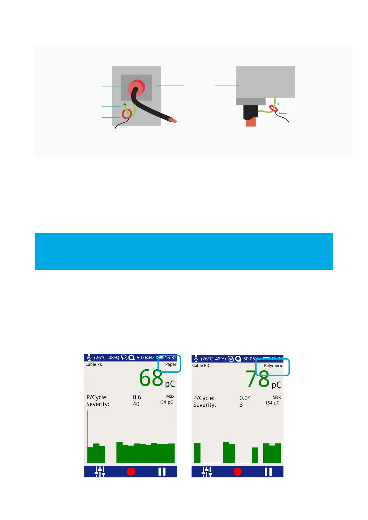
The cable type can be changed by pressing the text ‘paper’ or ‘polymeric’. The UTP2 green/amber/red
thresholds will change according to which cable insulation type has been selected.