CV3100 series and MINI series high performance general purpose inverter instruction manual
3-15
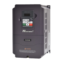
Diagram 3-11 AI2 terminal wiring
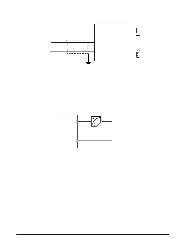
(3)Wiring of analog output terminal A01
Analog output terminal A01 with peripheric analog meter can indicate different
physical quantities; its wiring is shown as diagram 3-12.
Diagram 3-12 Analog output terminal wiring
Note: Because analog input/output signal is apt to suffer from external interference,
the wiring must be provided with the shielded cable; in addition, the cable shall
be earthed reliably and as short as possible.
wire near terminal
+
-
0~20mA
10V
AI2
GND
I
V
Grounding of shielded
CV3100
 Loading...