CV3100 series and MINI series high performance general purpose inverter instruction manual
3-16
3.6.4 Wiring of communication terminal
Communication interface of CV3100 inverter is the standard RS485 interface.
(1) The connection between remote-control keyboard and inverter is provided with
RS485 interface, when being connected, the remote-control keyboard plug is
directly connected to RS485 communication interface. The inverter keyboard and
remote-control keyboard can’t work simultaneously.
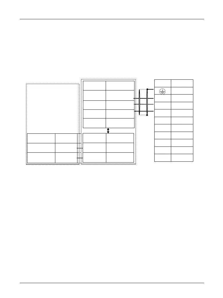
(2) Connection of inverter RS485 interface and upper machine:
Diagram 3-13 RS485-(RS485/232)-RS232 communication wiring
(3)As is shown in diagram 3-14 multi inverters may be connected togetherby
RS485 interface, they are controlled by PLC (or upper machine) that is used as
master. And as is shown in diagram 3-15 one inverter of them also can be used as
master, and other inverters are used as slave. With the addition of inverters, the
communication is apt to be interfered more easily, so we suggest the following
connecting ways:
 Loading...